Download
1 / 4
40 likes | 58 Views
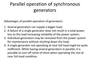
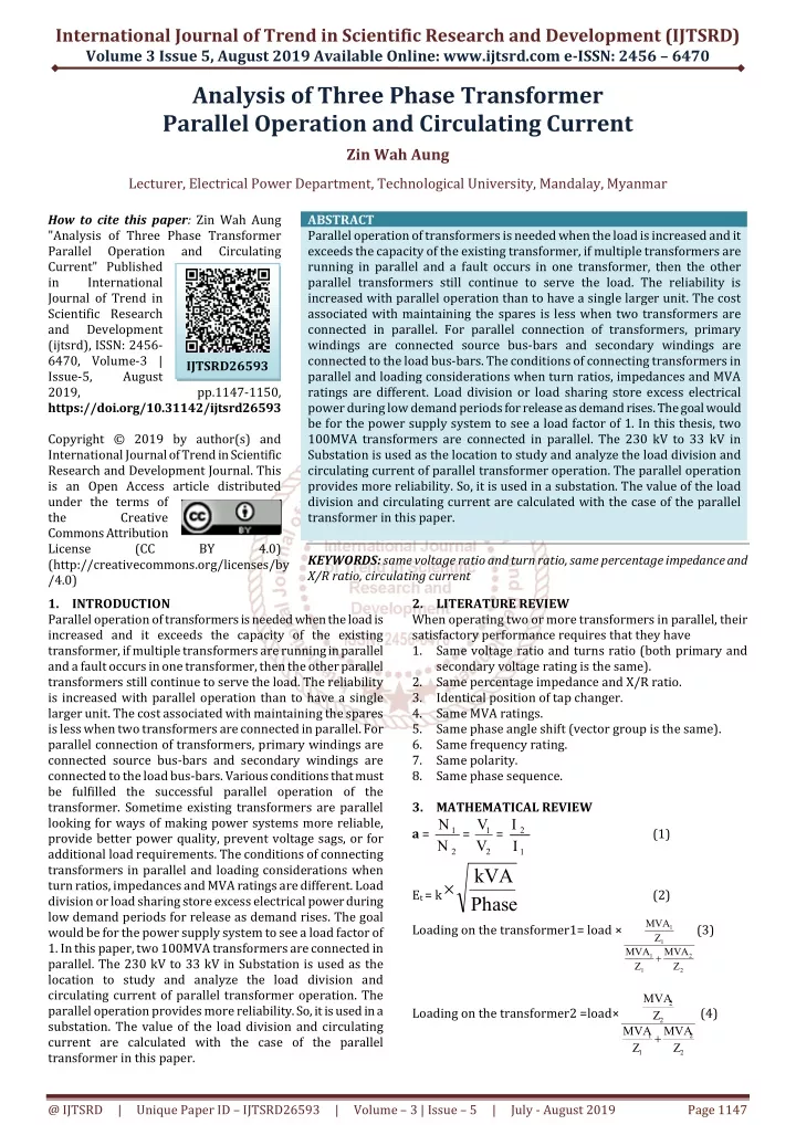
Parallel operation of transformers is needed when the load is increased and it exceeds the capacity of the existing transformer, if multiple transformers are running in parallel and a fault occurs in one transformer, then the other parallel transformers still continue to serve the load. The reliability is increased with parallel operation than to have a single larger unit. The cost associated with maintaining the spares is less when two transformers are connected in parallel. For parallel connection of transformers, primary windings are connected source bus bars and secondary windings are connected to the load bus bars. The conditions of connecting transformers in parallel and loading considerations when turn ratios, impedances and MVA ratings are different. Load division or load sharing store excess electrical power during low demand periods for release as demand rises. The goal would be for the power supply system to see a load factor of 1. In this thesis, two 100MVA transformers are connected in parallel. The 230 kV to 33 kV in Substation is used as the location to study and analyze the load division and circulating current of parallel transformer operation. The parallel operation provides more reliability. So, it is used in a substation. The value of the load division and circulating current are calculated with the case of the parallel transformer in this paper. Zin Wah Aung "Analysis of Three Phase Transformer Parallel Operation and Circulating Current" Published in International Journal of Trend in Scientific Research and Development (ijtsrd), ISSN: 2456-6470, Volume-3 | Issue-5 , August 2019, URL: https://www.ijtsrd.com/papers/ijtsrd26593.pdf Paper URL: https://www.ijtsrd.com/engineering/electrical-engineering/26593/analysis-of-three-phase-transformer-parallel-operation-and-circulating-current/zin-wah-aung<br>

E N D
International Journal of Trend in Scientific Research and Development (IJTSRD) Volume 3 Issue 5, August 2019 Available Online: www.ijtsrd.com e-ISSN: 2456 – 6470 Analysis of Three Phase Transformer Parallel Operation and Circulating Current Zin Wah Aung Lecturer, Electrical Power Department, Technological University, Mandalay, Myanmar How to cite this paper: Zin Wah Aung "Analysis of Three Phase Transformer Parallel Operation Current" Published in International Journal of Trend in Scientific Research and Development (ijtsrd), ISSN: 2456- 6470, Volume-3 | Issue-5, August 2019, https://doi.org/10.31142/ijtsrd26593 Copyright © 2019 by author(s) and International Journal of Trend in Scientific Research and Development Journal. This is an Open Access article distributed under the terms of the Creative Commons Attribution License (CC (http://creativecommons.org/licenses/by /4.0) 1.INTRODUCTION Parallel operation of transformers is needed when the load is increased and it exceeds the capacity of the existing transformer, if multiple transformers are running in parallel and a fault occurs in one transformer, then the other parallel transformers still continue to serve the load. The reliability is increased with parallel operation than to have a single larger unit. The cost associated with maintaining the spares is less when two transformers are connected in parallel. For parallel connection of transformers, primary windings are connected source bus-bars and secondary windings are connected to the load bus-bars. Various conditions that must be fulfilled the successful parallel operation of the transformer. Sometime existing transformers are parallel looking for ways of making power systems more reliable, provide better power quality, prevent voltage sags, or for additional load requirements. The conditions of connecting transformers in parallel and loading considerations when turn ratios, impedances and MVA ratings are different. Load division or load sharing store excess electrical power during low demand periods for release as demand rises. The goal would be for the power supply system to see a load factor of 1. In this paper, two 100MVA transformers are connected in parallel. The 230 kV to 33 kV in Substation is used as the location to study and analyze the load division and circulating current of parallel transformer operation. The parallel operation provides more reliability. So, it is used in a substation. The value of the load division and circulating current are calculated with the case of the parallel transformer in this paper. ABSTRACT Parallel operation of transformers is needed when the load is increased and it exceeds the capacity of the existing transformer, if multiple transformers are running in parallel and a fault occurs in one transformer, then the other parallel transformers still continue to serve the load. The reliability is increased with parallel operation than to have a single larger unit. The cost associated with maintaining the spares is less when two transformers are connected in parallel. For parallel connection of transformers, primary windings are connected source bus-bars and secondary windings are connected to the load bus-bars. The conditions of connecting transformers in parallel and loading considerations when turn ratios, impedances and MVA ratings are different. Load division or load sharing store excess electrical power during low demand periods for release as demand rises. The goal would be for the power supply system to see a load factor of 1. In this thesis, two 100MVA transformers are connected in parallel. The 230 kV to 33 kV in Substation is used as the location to study and analyze the load division and circulating current of parallel transformer operation. The parallel operation provides more reliability. So, it is used in a substation. The value of the load division and circulating current are calculated with the case of the parallel transformer in this paper. KEYWORDS: same voltage ratio and turn ratio, same percentage impedance and X/R ratio, circulating current and Circulating IJTSRD26593 pp.1147-1150, BY 4.0) 2.LITERATURE REVIEW When operating two or more transformers in parallel, their satisfactory performance requires that they have 1.Same voltage ratio and turns ratio (both primary and secondary voltage rating is the same). 2.Same percentage impedance and X/R ratio. 3.Identical position of tap changer. 4.Same MVA ratings. 5.Same phase angle shift (vector group is the same). 6.Same frequency rating. 7.Same polarity. 8.Same phase sequence. 3.MATHEMATICAL REVIEW N = V 1 I kVA Loading on the transformer1= load × I V= 2 1 1 a = (1) N 2 2 Et = k (2) Phase MVA (3) 1 Z 1 MVA MVA 1 2 Z Z 1 2 MVA 2 Loading on the transformer2 =load× (4) Z 2 MVA MVA 1 2 Z Z 1 2 @ IJTSRD | Unique Paper ID – IJTSRD26593 | Volume – 3 | Issue – 5 | July - August 2019 Page 1147
International Journal of Trend in Scientific Research and Development (IJTSRD) @ www.ijtsrd.com eISSN: 2456-6470 Table3. Transformer Tap Position Number of Tap 1 2 3 4 5 6 7 8 9 10 11 12 13 14 15 16 17 2 V b Zb = (5) Voltage 260360 256565 252770 248957 245180 241385 237590 233795 Normal tap 226205 222410 218615 214820 221025 207230 203435 199640 S b Z1 Z2 Z =%Z1×Zb (6) =%Z2×Zb (7) 2 2 R X (8) %Z 1 %R = (9) 2 X 1 R X %X1 = %R (10) R Let %e=difference in voltage ratio expressed in percentage MVA Table4. Actual Data of Loading in Substation Time Interval Loading of Transformer 1 of normal and k = (11) MVA 2 6 PM to 11 PM 126 MVA Circulating current, %Ic = 11 PM to 8 AM 50 MVA 100 %e (12) 2 2 %R k %R %Z k %Z 8 AM to 6 PM 92 MVA 1 2 1 2 4.RESULTS CIRCULATING CURRENT OF PARREL TRANSFORMER OPERATION 4.1 Same voltage ratio and Turn ratio 1 N Table1. Transformer Impedance IEC 60076 Percent Impedance %Z <0.630 0.631-1.25 1.251-3.15 3.151-6.3 6.301-12.5 12.501-25.0 25.001-200 13.5 >200 Table2.The impedance of Two Windings Distribution Transformers MVA Rating Percent Impedance %Z X/R Ratio 20 57 74 80 120 125 180 255 14.8 4.2.Same Percentage Impedance and X/R Ratio Case 1: Equal Impedance, Ratio and Same MVA Capacity of Transformer 1 Capacity of Transformer 2 % impedance, Z1 =13.5% % impedance, Z2 =13.5% Voltage ratio the same, Total load =200MVA Loading on the transformer 1 =100 MVA Loading on the transformer 2 =100 MVA Tap of transformer 1 = 0 (Normal tap) Tap of transformer 2 = 0 (Normal tap) Different voltage ratio = % e = 0 Circulating current, % Ic=0 Case 2: Equal Impedance, Ratios and different MVA Capacity of Transformer 1 Capacity of Transformer 2 % impedance, Z1 % impedance, Z2 Total load =137 MVA Total load =137 MVA Loading on the transformer 1=80MVA Loading on the transformer 2=57MVA Circulating current, % Ic =0 Case 3: Unequal Impedance but Same Ratio and MVA Capacity of Transformer 1 Capacity of Transformer 2 % impedance, Z1 % impedance, Z2 Voltage ratio the same, Total load =200 MVA Loading on the transformer 1=124 MVA Loading on the transformer2 = 76 MVA To calculate circulating current, , % Ic=0 DATA OF LOAD DIVISION AND =100MVA =100MVA N=7 2 X/R Ratio 1.5 3.5 6.0 8.5 13.0 20.0 45.0 Tolerance on %Z ±10 ±10 ±10 ±10 ±10 ±7.5 ±7.5 MVA Rating 4.0 5.0 6.25 7.15 8.35 10.0 =80MVA =57MVA =18.9 % =18.9 % By agreement 10 18.2 8.9 18.9 22.5 13.1 22.2 13 34 25 35 63 52 38 43 =100MVA =100MVA =13.5 % =22 % @ IJTSRD | Unique Paper ID – IJTSRD26593 | Volume – 3 | Issue – 5 | July - August 2019 Page 1148
International Journal of Trend in Scientific Research and Development (IJTSRD) @ www.ijtsrd.com eISSN: 2456-6470 Case 4: Unequal Impedance and MVA but Same Ratio Capacity of transformer1, (MVA1) Capacity of transformer2, (MVA2) % Impedance, Z1 % Impedance, Z Voltage ratio the same, Total load = 180 MVA Loading on the transformer 1 = 115MVA Loading on the transformer 2 = 65MVA Circulating current, % Ic =0 Case 5: Equal Impedance and MVA but Unequal Ratio Capacity of transformer1, (MVA1) Capacity of transformer 2, (MVA2) % Impedance, Z1 =13.5% % Impedance, Z2 =13.5% Total load =200 MVA Loading on the transformer 1=100 MVA Loading on the transformer 1=100 MVA Circulating current, % Ic =6.1% =100 MVA =80 MVA = 13.5 % = 18.9 % =100 MVA =100 MVA Table5. Resulting of Circulating Current Tap Different voltage ratio Circulating current 1 1.65 2 3.3 3 4.95 4 6.6 5 8.25 6 9.9 7 11.6 8 13.2 9 - 10 1.65 11 3.3 12 4.95 13 6.6 14 8.25 15 9.9 16 11.6 17 13.2 6.1 12.2 `18.3 24.4 30.5 36.7 42.8 48.9 - 6.1 12.2 18.3 24.4 30.5 36.7 42.8 48.9 Case 6: Unequal Impedance, MVA Ratings and Different Ratios Capacity of transformer1, (MVA1) Capacity of transformer2, (MVA2) % Impedance, Z1 = 13.5 % % Impedance, Z2 =18.9 % Total load =180 MVA Loading on the transformer 1 = 115MVA Loading on the transformer 2 65MVA Circulating current, % Ic =4.4% =100 MVA =80 MVA Table5. Resulting of Circulating Current Tap Different voltage ratio Circulating current 1 1.65 2 3.3 3 4.95 4 6.6 5 8.25 6 9.9 7 11.6 8 13.2 9 - 10 1.65 11 3.3 12 4.95 13 6.6 14 8.25 15 9.9 16 11.6 17 13.2 4.44 8.89 13.33 17.77 22.22 26.66 31.25 35.54 - 4.44 8.89 13.33 17.77 22.22 26.66 31.24 35.54 @ IJTSRD | Unique Paper ID – IJTSRD26593 | Volume – 3 | Issue – 5 | July - August 2019 Page 1149
International Journal of Trend in Scientific Research and Development (IJTSRD) @ www.ijtsrd.com eISSN: 2456-6470 Table4.7. Resulting Table of Six Cases Loading on Transformer1 Transformer2 100 MVA 100 MVA 80 MVA 57 MVA 124 MVA 76 MVA 115 MVA 65 MVA 100 MVA 100 MVA 115 MVA 65 MVA Loadingon Circulating Current, Ic (%) 0 0 0 0 Percent Impedance, % Z1 13.5% 18.9% 13.5% 13.5% 13.5% 13.5% % Z2 13.5% 18.9% 22% 18.9% 13.5% 18.9% 6.1 to 48.9 (According to Tap Ratio) 4.44 to 35.54 (According to Tap Ratio) 5.CONCLUSION Loading considerations for paralleling transformers are simple unless MVA, percent impedances or ratios are different. When parallel transformer turn ratios and percent impedances are the same, equal load division will exist on each transformer. When paralleled transformer MVA ratings are the same but the percent impedances are different, then unequal load division will occur. The same is true for unequal percent impedances and unequal MVA. Circulation currents only exist if the turn ratios do not match on each transformer. The magnitude of the circulating currents will also depend on the X/R ratios of the transformers. Delta-delta to delta-wye transformer paralleling should not be attempted. 6.ACKNOWLEDGMENT The author deeply wants to express special appreciation and heart-left thanks to Dr. Yadana Aung, Professor and Head the Department of Electrical Power Engineering, Technological University (Mandalay) for her willingness to share her ideas and helpful suggestions on this paper writing. 7.REFERENCES [1][25JP] Johnson and Phillips LTD, The J&P Transformer Book,1925 [2][61KJ] Kingsley. Jr, Electrical Machinery,1961. [3][43J.W] John Wiley and Sons, Magnetic Circuit and Transformer, 1943. [4][05BL] B. LTheraja, A Text Book of Electrical Technology,2005 [5][49MG] Stay M. G, the performance and design of alternating current machines, 1949. @ IJTSRD | Unique Paper ID – IJTSRD26593 | Volume – 3 | Issue – 5 | July - August 2019 Page 1150