Download
1 / 6
70 likes | 84 Views
Photovoltaic PV energy and wind energy are two important renewable energy sources utilized for its easy access, availability, non polluting, noiseless and maintenance free. Another source Fuel Cell FC is utilized to generate controlled energy source with battery used as a backup unit. Hybrids systems are superior compared to single sourced systems provide high quality and adequate power. These systems are having a complex system topology, significant power losses, high initial cost, inefficient energy conversion and large size. In this paper, good performance, high quality, low harmonics, and efficient integrated DC DC boost converter for renewable power conversion system with minimum switches is analyzed. S. Kasthuri "Analysis of DC-DC Boost Converter for Hybrid Power Generating System" Published in International Journal of Trend in Scientific Research and Development (ijtsrd), ISSN: 2456-6470, Volume-2 | Issue-5 , August 2018, URL: https://www.ijtsrd.com/papers/ijtsrd18297.pdf Paper URL: http://www.ijtsrd.com/engineering/electrical-engineering/18297/analysis-of-dc-dc-boost-converter-for-hybrid-power-generating-system/s-kasthuri<br>

E N D
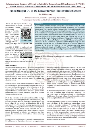
International Research Research and Development (IJTSRD) International Open Access Journal DC Boost Converter for Hybrid Power Generating System S. Kasthuri Lecturer (Senior Grade), Department of Electrical and Electronics Engineering, Sakthi Polytechnic College, Sakthi Nagar, Erode, Tamil Nadu, India International Journal of Trend in Scientific Scientific (IJTSRD) International Open Access Journal ISSN No: 2456 ISSN No: 2456 - 6470 | www.ijtsrd.com | Volume 6470 | www.ijtsrd.com | Volume - 2 | Issue – 5 Analysis of DC-DC Boost Converter for Hybrid Power Lecturer (Senior Grade), Department of Electrical and Electronics Engineering, Sakthi Polytechnic College, Sakthi Nagar, Erode, Lecturer (Senior Grade), Department of Electrical and Electronics Engineering, Tamil Nadu, India ABSTRACT Photovoltaic (PV) energy and wind energy are two important renewable energy sources utilized for its easy access, availability, non-polluting, noiseless and maintenance-free. Another source Fuel Cel utilized to generate controlled energy source with battery used as a backup unit. Hybrids systems are superior compared to single sourced systems provide high quality and adequate power. These systems are having a complex system topology, signifi losses, high initial cost, inefficient energy conversion and large size. In this paper, good performance, high quality, low harmonics, and efficient integrated DC DC boost converter for renewable power conversion system with minimum switches is analyzed. KEYWORD: Photovoltaic, Fuel Cell, Proportional Integral Derivative controller, Modulation, Zero Voltage Transition, Total Harmonic Distortion. I. INTRODUCTION The traditional converter operates on hard switching; the pulse of current and voltage signal either goes from high to low value or vice-versa. During the transition period, switching loss occurs and creates a large value of electromagnetic interference. To rectify this, soft switching technique is adopted and switching losses are reduced. A Proportional-Integral-Derivative (PID) controller is a feedback mechanism of control loop used in industrial control systems with voltage deviation, noise and error measurement leads to oscillation of the duty cycle in steady state condition. this, decoupling network is designed using state space this, decoupling network is designed using state space modeling and controllers are properly designed for this multi-input multi-output converter. In the conventional boost converters, stress on the switch is more which in turn reduces the the switches and increases the losses. It may be reduced by proper design of circuit topology and inductors arrangement. The poor quality of output power due to the harmonics can be improved in the multi boost converter fed Space Vector Modulation (SVM) inverter. The objectives of analysis is, ?To develop a new converter topology and its control method, this will be effective and efficient to harvest maximum energy without undue loss. ?To address the problem of power requirement in the future and the challenges for power generation using renewable energy sources. ?To study the fundamentals of available renewable energy sources, existing converter topologies and its controller design. ?To design, analyze and control the most efficient multi-port DC-DC boost converter. Several power converters are proposed in this paper to overcome the constraints of PV systems. A produced device that was highly efficient, little stress on the devices and less current ripple DC used for solar power systems [1]. Despite the advantages of PV system, the conversion technologies used in solar energy generation are technologies used in solar energy generation are Photovoltaic (PV) energy and wind energy are two important renewable energy sources utilized for its modeling and controllers are properly designed for output converter. polluting, noiseless and free. Another source Fuel Cell (FC) is utilized to generate controlled energy source with battery used as a backup unit. Hybrids systems are superior compared to single sourced systems provide high quality and adequate power. These systems are having a complex system topology, significant power losses, high initial cost, inefficient energy conversion and large size. In this paper, good performance, high quality, low harmonics, and efficient integrated DC- DC boost converter for renewable power conversion In the conventional boost converters, stress on the switch is more which in turn reduces the lifecycle of the switches and increases the losses. It may be reduced by proper design of circuit topology and The poor quality of output power due to the harmonics can be improved in the multi-port DC-DC ector Modulation (SVM) analyzed. To develop a new converter topology and its control method, this will be effective and efficient to harvest maximum energy without undue loss. To address the problem of power requirement in e future and the challenges for power generation sources. To study the fundamentals of available renewable energy sources, existing converter topologies and Photovoltaic, Fuel Cell, Proportional Derivative controller, Modulation, Zero Voltage Transition, Total Harmonic Integral Space Space Vector Vector The traditional converter operates on hard switching; and voltage signal either goes versa. During the transition period, switching loss occurs and creates a large value of electromagnetic interference. To rectify this, soft switching technique is adopted and To design, analyze and control the most efficient DC boost converter. Several power converters are proposed in this paper to overcome the constraints of PV systems. A produced device that was highly efficient, little stress on the devices and less current ripple DC-DC converter is solar power systems [1]. Derivative (PID) controller is a feedback mechanism of control loop used in industrial control systems with voltage deviation, noise and error measurement leads to oscillation of the duty cycle in steady state condition. To overcome Despite the advantages of PV system, the conversion @ IJTSRD | Available Online @ www.ijtsrd.com @ IJTSRD | Available Online @ www.ijtsrd.com | Volume – 2 | Issue – 5 | Jul-Aug 2018 Aug 2018 Page: 2325
International Journal of Trend in Scientific Research and Development (IJTSRD) ISSN: 2456-6470 costly, in addition to having scalability problems that is inherent to support a complete energy system [2]. A Zero Voltage Transition (ZVT) based power converter is used with two inputs, PV and battery acts as a voltage source [3]. A renewable energy system is designed with PV array, wind turbine and FC that can operate as grid connected and stand alone models. In their models, an independent power processing stage is deployed to process each power source before being delivered to the DC bus [4]. A soft-switching interleaved boost converter is consisting of two shunted conversion units and an auxiliary inductor [5].A novel multi-input DC-DC converter based on the transformer flux additively concept is used [6]. Subsequently, researchers proposed design for bidirectional converters to connect to the storage. Nevertheless, these models are found to be highly complex with a high cost attributed to it because of the several conversion stages and devices which were used between the individual converters. A three port converter is used as a multiple converters and they have superior system efficiency, faster response, compact packaging and unified power flow management [7]. A three input novel DC–DC boost converter used for hybrid energy generation applications can able to create current source type in the input side sources that may control the respective input voltages [8]. In this paper, three input DC-DC converter for grid connected hybrid power system fed from full bridge inverter with bidirectional flow is utilized. A.Methodology In the conventional structure, there usually exists a common high-voltage or low-voltage dc bus interconnecting multiple sources. Separate dc-dc conversion stages are often used for individual sources. The main structural concern of a hybrid power source is the position of the storage like batteries. An advantage of this configuration is that it is possible to choose an optimal voltage for the storage. Figure 1 shows the different storage positions in a hybrid power source. elementary boost Figure 1: Different storage positions in a hybrid power source showing (a) Parallel with main source (b) On the main power flow path (c) Connected to DC bus through a bidirectional DC-DC converter. [9] B.Multiport Structure The multiport structure is emerging as an alternative for hybrid power sources. It is different from the conventional one [10]. The whole system is viewed as a single power processing stage that has multiple interfacing ports as shown in figure 2. A multiport DC-DC converter is used to interface numerous power sources and storage devices. It regulates the system voltages and manages the power flow between the sources and the storage elements. Figure 2: Multiport system structure @ IJTSRD | Available Online @ www.ijtsrd.com | Volume – 2 | Issue – 5 | Jul-Aug 2018 Page: 2326
International Journal of Trend in Scientific Research and Development (IJTSRD) ISSN: 2456-6470 II. In this paper, a DC–DC boost converter that uses the wind, PV, FC and battery input sources for hybrid power system is proposed. The proposed converter structure consists of three unidirectional input ports, which acts as the input renewable sources; a bidirectional input source as a storage element and an output to load as shown in Figure 3. Proposed Converter Topology autonomous working of input power sources and increased output voltage. The input power are distributed both to the load and battery is done independently.Therefore, the proposed converter can be used as powerful substitute for the multiple sources and battery hybrid power systems. A. Modes of Operation In the first mode of operation, power is supplied to the load by wind and PV cell, without FC and battery [12]. At this point, switches S1, S2 and S3 are switched ON. The duty ratio of switch S1 should be less than duty ratio of S2 and S3.Turning ON of all switches accordingly charges the inductors L1 and L2. Switching OFF of three switches, discharging of inductors through the diodes D1 and D2 to the load. In the second mode, the load receives power from PV, FC and by discharging the battery. The switches S2, S4 and S5 are switched ON and thus charging of the inductors L2 and L3. In the beginning, the switches S2 is switched OFF, then the switches S4 and S5 are switched OFF. The current flows through the diodes D2 and D3 by discharging the energy stored in inductors L2 & L3. In the third mode, the load receives power from wind and FC. The switches S1 , S4 and S5 are switched ON resulting in charging of inductors L1 and L3.The current flows through the diodes D1 and D3 by discharging the energy stored in inductors L1 & L3. Small signal modeling of the mode-1 operation is, C? Small signal modeling of the mode-2 operation is, di2 dt+ r? iL? = ?d?− d??Vpv + ?1 − d???Vpv − V?? + d??Vpv + Vb? di3 dt+ r? iL? = ?d?− d??Vfc + ?1 − d???Vfc − V? ? + d??Vfc + Vb? Small signal modeling of the mode-3 operation is, C? Figure 3: Block Diagram of the Proposed Converter Photovoltaic cell and Fuel cell input ports are acting as constant current source as well as to build up the input voltages. This is a unique arrangement of five power MOSFET switches; each switch uses different duty ratios thereby controlled individually. The excess power generated through the PV and FC is given to the battery for storage. Based on energy utilization, four operating modes of the converter are designed [11]. ??? ??+?? ??= iL??1 − d?? + iL??1 − d?? (01) Figure 4: Proposed DC-DC Boost Converter Topology Figure 4 shows the proposed DC-DC boost converter topology. To make efficient input sources, the switch S2 and S3 should not be turned off before S1 is switched off. Otherwise L2 and L3 will continue to store energy even S1 is switched off and produces the unwanted output. To ensure that S1 remain off before starting S2 and S3, the duty ratios 2 and 3 should be greater than duty ratio 1. Similar to conventional type boost converters, diodes D1, D2 and D3 conduct with corresponding switches S1, S2 and S3 in a complementary mode. The advantages are, bidirectional power flow to battery, simple structure, low components, centralized control, transformer less L? (02) L? (03) ??? ??+?? ??= iL??1 − d?? + iL??1 − d?? (04) operation, stable, @ IJTSRD | Available Online @ www.ijtsrd.com | Volume – 2 | Issue – 5 | Jul-Aug 2018 Page: 2327
International Journal of Trend in Scientific Research and Development (IJTSRD) ISSN: 2456-6470 Compared to mode 1, the peak load demand is met in mode 4 and the switches S1, S2, S3, S4 and S5 are switched ON. During this period, the inductors L1, L2 and L3 are charged. At first, the switch S1 is switched OFF to keep the duty ratio D1 less than the others. Afterwards, the switches S2 and S5 are switched OFF for enabling the battery to move into the charging mode with extra power. Finally, the switches S4 and S3 are switched off and the current flows through the diodes D1, D2 and D3 by discharging the energy stored in inductors L1, L2 and L3. Small signal modeling of the mode-4 operation is, L? ?d?− d???Vpv − Vb? (05) L? ?d?− d???Vfc − Vb? (06) C? d?? Where, d1, d2, d3 and d4 are duty ratios of corresponding switches. VPV, VW, Vfc and Vb are the voltages in the PV, Wind, FC and battery respectively. B.Power Management The power management flowchart is shown in Figure 5. Consider the initial load demand of 750 W. At first simulation mode, the wind energy and photovoltaic cell meet the load demand of 750 W. If the wind availability is very less for satisfying load demand, then the wind energy source is shut down fully in the first mode. In the second simulation mode, fuel cell is switched on and discharging of battery is started. If the availability of sunlight is very less to meet out the load demand, then the solar energy source is shut down fully. In the third simulation mode, fuel cell is switched on and in fourth simulation mode, the power generation is done by wind, PV and FC in order to meet the maximum load demand up to 1500 W. In the fourth mode, extra power generated by these sources is utilized for charging the battery [13]. ??? ??+ r? iL?= d?Vpv + ?1 − d???Vpv − V0? + ??? ??+ r? iL?= d?Vfc + ?1 − d???Vfc − V?? + ??? ??+?? ??= iL??1 − d?? + iL??1 − d?? + iL??1 − (07) Figure 5: Power Management flowchart C.State Space Modeling and Control In this converter topology, a control variable of input differs from one mode to another mode. To reduce the difficulties associated with controller design of this converter, multi input - multi output controller design is used. The average state space modeling value is obtained by taking the duty ratios d1, d2, d3, d4 and d5 as control variables. During the mode -1 operation, iL1, iL2 and Vo are considered to derive the state space model. The system was investigated by using Matlab simulation software [14]. Stable operation of this converter is obtained using properly designed closed loop control system. For loop K=0.81765 the phase margin of 600 and gain margin of 10db is obtained. Graphical user interface model is used to represent the closed loop transfer function of boost converter. This transfer function is obtained from input 1 to output 1 and its response are shown in Figure 6. The increased loop gain makes the system to be unstable. Similarly, the stable of the converter is obtained in all the operating points. @ IJTSRD | Available Online @ www.ijtsrd.com | Volume – 2 | Issue – 5 | Jul-Aug 2018 Page: 2328
International Journal of Trend in Scientific Research and Development (IJTSRD) ISSN: 2456-6470 Figure 6: Closed Loop Response of Proposed Converter SImulation Results In mode 4 operation, the boosted voltage from DC- DC converter is around 515 V to meet the peak power demand as shown in Figure 7. During this mode, the maximum power generated is 1500 W. Figure 8: Efficiency comparisons with Proposed Converter III. The current Total Harmonic Distortion (THD) for the proposed system is calculated from FFT analysis and it is proved that the performance of proposed converter is improved with fewer harmonic present in the output. IV. CONCLUSION In this paper, the design of multi-port DC-DC boost converter with different investigated. The small signal modeling and state space modeling is analyzed for stable operation of the converter. In this proposed multi-port DC-DC boost converter for hybrid power conversion, 1% of efficiency improvement is achieved. Further the quality of output voltage is improved with fewer value of THD when compared to existing system. REFERENCES 1.Chiu, H-J, Yao, C-J & Lo, Y-K 2009, ‘A DC/DC converter topology for renewable energy systems’, International journal of circuit theory and applications, vol. 37, no. 3, pp. 485-495. 2.Lewis, NS 2007,‘Toward cost-effective solar energy use’, Science, vol. 315, no. 5813, pp. 798- 801. 3.Wai, R-J, Lin, C-Y, Liaw, J-J & Chang, Y-R 2011, ‘Newly designed converter,’ in IEEE Transactions on Industrial Electronics, vol. 58, no. 2, pp. 555–566. 4.Coelho, RF, Schimtz, L & Martins, DC 2011, ‘Grid-Connected PV -Wind-Fuel Cell Hybrid operating modes is Figure 7: DC Link Voltage of Proposed Converter In this proposed multi-port DC-DC converter, the efficiency of the converter topology is verified in terms of power. Graphical representation of the efficiency comparison between proposed converter, interleaved converter and conventional converter is shown in Figure 8. It shows that the proposed converter efficiency is 1% more than the conventional type converters and slightly higher than the interleaved converter. ZVS multi-input @ IJTSRD | Available Online @ www.ijtsrd.com | Volume – 2 | Issue – 5 | Jul-Aug 2018 Page: 2329
International Journal of Trend in Scientific Research and Development (IJTSRD) ISSN: 2456-6470 10.H. Tao, “Integration of sustainable energy sources through power electronic converters in small distributed electricity generation systems,” Ph.D. dissertation, Eindhoven University of Technology (TU/e), Eindhoven, The Netherlands, Jan. 2008. 11.Veena, P, Indragandhi, V, Jeyabharath, R, 2013, ‘An Interleaved Soft Switching Boost Converter with Full Bridge Inverter for Photovoltaic power generation’, Research Sciences, Engineering & Technology, vol. 6, no. 22, pp.4204-4210. 12.Nejabatkhah, F, Danyali, S, Hosseini, S H, Sabahi, M & Niapour, SM 2012, ‘Modelling and Control of a New Three-Input DC–DC Boost Converter for Hybrid PV/FC/Battery Power System’, IEEE Transactions on power electronics, vol. 27, no. 5, pp. 2309 – 2324. 13.Indragandhi, V, Veena, P, Jeyabharath, R (Under Review), ‘Steady State Analysis and Power Management of DC-DC Boost Converter for PV/Wind/FC/Battery Power Generation’, IEEE Transactions on Industrial Electronics. 14.T. K. Santhosh, K. Natarajan and C. Govindaraju, “Synthesis and Implementation of a Multi-Port DC/DC Converter for Hybrid Electric Vehicles,“ Journal of Power Electronics, Vol. 15, No. 5, pp. 1178-1189, September 2015. System Employing a Super capacitor Bank as Storage Device to Supply a Critical DC Load,’ IEEE Telecommunications Energy International Conference (INTELEC), pp. 1-10. 5.Hsieh, Y-C, Hsueh, T-C, & Yen, H-C 2009, ‘An Interleaved Boost Converter with Zero Voltage Transition’, IEEE Transactions Electronics, vol. 24, no. 4, pp. 973-978. 6.Chen, Y-M, Liu, Y-C & Wu, F-Y 2002, ‘Multi- Input DC/DC converter based on the multi winding transformer for renewable energy applications’, IEEE Transactions on Industry Applications, vol. 38, no. 4, pp. 1096 – 1104. 7.Tao, H, Duarte, J L & Hendrix, M 2008, ‘Multiport converters for hybrid power sources’, IEEE Power electronics specialists conference (PESC 2008), pp. 3412-3418. 8.Tao, H, Duarte, J L & Hendrix, M 2008, ‘Multiport converters for hybrid power sources’, IEEE Power electronics specialists conference (PESC 2008), pp. 3412-3418. 9.Haimin Tao, Jorge L. Duarte, and Marcel A. M. Hendrix, “Multiport Converters for Hybrid Power Sources,” IEEE Annual Power Electronics Specialists Conference July 2008. on Power Journal of Applied @ IJTSRD | Available Online @ www.ijtsrd.com | Volume – 2 | Issue – 5 | Jul-Aug 2018 Page: 2330