Download
1 / 4
40 likes | 42 Views
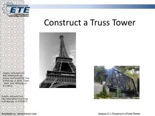
A transmission tower or power tower alternatively electricity pylon or variations is a tall structure, usually a steel lattice tower, used to support an overhead power line. Ishrat Jahan Siddiqui | Nitesh Kushwaha "A Review Study on Comparative Study on Single Web System Truss Tower with Portal System Truss Tower" Published in International Journal of Trend in Scientific Research and Development (ijtsrd), ISSN: 2456-6470, Volume-4 | Issue-1 , December 2019, URL: https://www.ijtsrd.com/papers/ijtsrd29799.pdf Paper URL: https://www.ijtsrd.com/engineering/civil-engineering/29799/a-review-study-on-comparative-study-on-single-web-system-truss-tower-with-portal-system-truss-tower/ishrat-jahan-siddiqui<br>

E N D
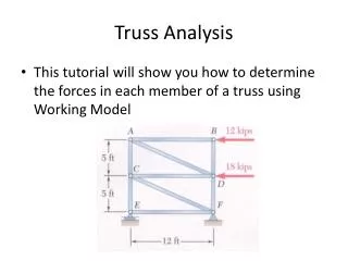
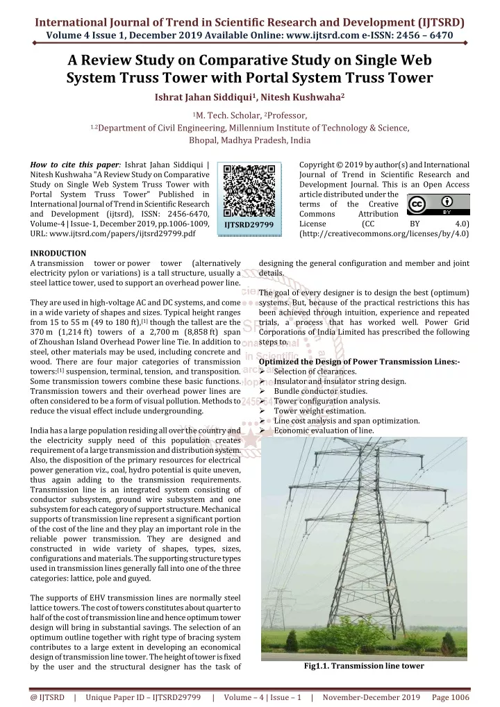
International Journal of Trend in Scientific Research and Development (IJTSRD) Volume 4 Issue 1, December 2019 Available Online: www.ijtsrd.com e-ISSN: 2456 – 6470 A Review Study on Comparative Study on Single Web System Truss Tower with Portal System Truss Tower Ishrat Jahan Siddiqui1, Nitesh Kushwaha2 1M. Tech. Scholar, 2Professor, 1.2Department of Civil Engineering, Millennium Institute of Technology & Science, Bhopal, Madhya Pradesh, India How to cite this paper: Ishrat Jahan Siddiqui | Nitesh Kushwaha "A Review Study on Comparative Study on Single Web System Truss Tower with Portal System Truss Tower" Published in International Journal of Trend in Scientific Research and Development (ijtsrd), ISSN: 2456-6470, Volume-4 | Issue-1, December 2019, pp.1006-1009, URL: www.ijtsrd.com/papers/ijtsrd29799.pdf INRODUCTION A transmission tower or power tower (alternatively electricity pylon or variations) is a tall structure, usually a steel lattice tower, used to support an overhead power line. They are used in high-voltage AC and DC systems, and come in a wide variety of shapes and sizes. Typical height ranges from 15 to 55 m (49 to 180 ft),[1] though the tallest are the 370 m (1,214 ft) towers of a 2,700 m (8,858 ft) span of Zhoushan Island Overhead Power line Tie. In addition to steel, other materials may be used, including concrete and wood. There are four major categories of transmission towers:[1] suspension, terminal, tension, and transposition. Some transmission towers combine these basic functions. Transmission towers and their overhead power lines are often considered to be a form of visual pollution. Methods to reduce the visual effect include undergrounding. India has a large population residing all over the country and the electricity supply need of this population creates requirement of a large transmission and distribution system. Also, the disposition of the primary resources for electrical power generation viz., coal, hydro potential is quite uneven, thus again adding to the transmission requirements. Transmission line is an integrated system consisting of conductor subsystem, ground wire subsystem and one subsystem for each category of support structure. Mechanical supports of transmission line represent a significant portion of the cost of the line and they play an important role in the reliable power transmission. They are designed and constructed in wide variety of shapes, types, sizes, configurations and materials. The supporting structure types used in transmission lines generally fall into one of the three categories: lattice, pole and guyed. The supports of EHV transmission lines are normally steel lattice towers. The cost of towers constitutes about quarter to half of the cost of transmission line and hence optimum tower design will bring in substantial savings. The selection of an optimum outline together with right type of bracing system contributes to a large extent in developing an economical design of transmission line tower. The height of tower is fixed by the user and the structural designer has the task of Copyright © 2019 by author(s) and International Journal of Trend in Scientific Research and Development Journal. This is an Open Access article distributed under the terms of the Creative Commons Attribution License (CC (http://creativecommons.org/licenses/by/4.0) BY 4.0) IJTSRD29799 designing the general configuration and member and joint details. The goal of every designer is to design the best (optimum) systems. But, because of the practical restrictions this has been achieved through intuition, experience and repeated trials, a process that has worked well. Power Grid Corporations of India Limited has prescribed the following steps to. Optimized the Design of Power Transmission Lines:- ?Selection of clearances. ?Insulator and insulator string design. ?Bundle conductor studies. ?Tower configuration analysis. ?Tower weight estimation. ?Line cost analysis and span optimization. ?Economic evaluation of line. Fig1.1.Transmission line tower @ IJTSRD | Unique Paper ID – IJTSRD29799 | Volume – 4 | Issue – 1 | November-December 2019 Page 1006
International Journal of Trend in Scientific Research and Development (IJTSRD) @ www.ijtsrd.com eISSN: 2456-6470 LITERATURE REVIEW [1]Siti Aisyah Kamarudin 2019 The increasing global population was demanded for more consumption of electricity. In Malaysia, it was reported that 17,790 megawatts (MW) was consumed in October 2017 due to high demand. The peak reading recorded is 0.011% increase compared to demand on April 2016 (17,788 MW). Following this, more transmission tower lines need to be developed to generate more electricity. Land acquisition is the main issue for constructing the new transmission tower because it requires a large area to set it up. The idea of optimization on the existing transmission tower helps in reducing cost for constructing the new structure. The aim of this study is to develop an optimal design of the transmission tower. A 275 kV transmission tower model is used in this study for analyzing and optimizing by using linear static and p-delta analysis. This optimization method is done by reducing tower members as well as increasing size of member's element. A modification and arrangement of the transmission tower members is referred to manual guidelines of EN1993-3-1 and ASCE 10-97. Two alternatives are being prepared to produce an optimal design and result shows that a reduction percentage in term of reduced number of bar members can be saved up to 34 %. [2]Kamarudin 2018 Demand for electricity is increasing as the population grows. Transmission towers need to be upgraded in order to satisfy these increasing demands for power supply. A study on the stability of the transmission tower is significant to make sure that the tower is stable and capable enough to transmit electricity due to high demand. In this paper, a review on analysis and design of the lattice steel structure of the overhead transmission tower together with its design as in ASCE and Euro code standard are presented. Two methods are introduced which are linear static analysis and p-delta analysis to compare its maximum internal force, maximum displacement as well as location for critical part of the tower when different loadings applied. In analysis, the tower model used for modelling and simulation is assumed as fully- beam and fully-truss. Standard code MS 1533:2000 is referred for wind loading calculation. It is found that the highest internal force is at the leg of the tower on a normal case with an angle of attack of wind is 45°. [3]S. B. Chaudhari1 2018 The transmission towers are constructed for transmitting the electricity from generation station to substations. The function of transmission tower is to support the conductor wires and ground wires at suitable distance and safe height from ground. Therefore transmission line towers should be designed considering both structural and electrical requirements for a safe and economical design. In this study an attempt is made to model, analyse and design a 220kV double circuit transmission line towers. STAAD Pro program is going to be used for analysis and design of the members of 220kV double circuit tower [4]Shubhank Gupta 2017 This paper presents the analysis and design of steel truss railway bridge of span 50 m. The bridge with same railway loadings of 32.5 tonne has been assigned in different types of truss sections to determine the best stable and economical section. Analysis and design is completed using tool staad pro to optimize the section and determine best stable sections for comparison. The design of structural members of the truss is done in accordance with provision of Indian railway standard code and Indian roads congress code. [5]Siddu Karthik 2016 Transmission line towers carry heavy electrical transmission conductors at a sufficient and safe height from ground. In addition to their self- weight they have to withstand all forces of nature like a strong wind, earthquake and snow load. Therefore, transmission line towers should be designed considering both structural requirements for a safe and economical design. [6]Ganesh Nadu 2016 The electrical transmission towers carry heavy electrical transmission conductors at a sufficient and safe height from ground. In addition to their self-weight they have to withstand all forces of nature like strong wind, earthquake and snow load. Therefore transmission line towers should be designed considering both structural requirements for a safe and economical design. . A model of the transmission tower used effective element types on various components of transmission tower for static and dynamic analysis. Further determine the static response and corresponding stress resultants of transmission tower structure due to wind load at one static instant time on vertical and transversely position of transmission tower using ANSYS. Also studied free vibrational or modal analysis characteristics of the transmission tower by determine the frequencies and mode shapes of transmission tower using ANSYS and validating the finite element based results with closed form solution. At last elaborate study on the transient dynamic analysis of transmission tower using ANSYS with emphasis on the evaluation of dynamic response of transmission tower due to time varying wind load with various wind velocity like displacement and axial force. Keywords: Transmission tower, FEM, ANSYS, static analysis, [7]T. Pramod Kumar, G. Phani Ram 2015 This research’s objective was to estimate the economic importance of the railway cum Road Bridge. This paper was carried out to find out the reduction in cost of construction by providing single bridge for both road as well as railways. The analysis and design phase of the project was done utilizing STAAD PRO V8i. It was observed that the construction of a single bridge reduced the cost of two separate bridges for road and railways; also land acquisition problem is reduced to some extent. [8]Siddu Karthik 2015 Transmission line towers carry heavy electrical transmission conductors at a sufficient and safe height from ground. In addition to their self- weight they have to withstand all forces of nature like a strong wind, earthquake and snow load. Therefore, transmission line towers should be designed considering both structural requirements for a safe and economical design. [9]Serkan Sahin 2014 The collapse of transmission towers involves a series of complex problems, including geometric nonlinearity, dynamic nonlinearity, and the failure of members. Simulation of the process of collapse is and electrical design calculation for and electrical and electrical nonlinearity, material @ IJTSRD | Unique Paper ID – IJTSRD29799 | Volume – 4 | Issue – 1 | November-December 2019 Page 1007
International Journal of Trend in Scientific Research and Development (IJTSRD) @ www.ijtsrd.com eISSN: 2456-6470 difficult using traditional finite element method (FEM), which is generated from continuum and variation principle, whereas the finite particle method (FPM) enforces equilibrium on each point. Particles are free to separate from one another, which is advantageous in the simulation of the structural collapse. This paper employs the finite particle method (FPM) to simulate the collapse of a transmission steel tower under earthquake ground motions; the three-dimensional (3D) finite particle model using MATLAB and the 3D finite element model using ANSYS of the transmission steel tower are established, respectively. And the static and elastic seismic response analyses indicate that the results of the FPM agree well with those of the FEM. To simulate the collapse of the transmission steel tower, a failure criterion based on the ideal elastic-plastic model and a failure mode are proposed. Finally, the collapse simulation of the transmission steel towers subjected to unidirectional earthquake ground motion and the collapse seismic fragility analysis can be successfully carried out using the finite particle method. The result indicates that the transmission steel tower has better seismic safety performance and anticollapse ability. [10]Gopi Sudam Punse 2014 In this project, an attempt has been made to make the transmission line more cost effective keeping in view to provide optimum electric supply for the required area by considering unique transmission line tower structure. The objective of this research is met by choosing a 220KV and 110KV Multi Voltage Multi Circuit with narrow based Self Supporting Lattice Towers with a view to optimize the existing geometry. Using STAAD PRO v8i analysis and design of tower has been carried out as a three dimensional structure. Then, the tower members are designed.ign. [11]Y. M. Ghugal , U. S. Salunkhe 2011 The four legged lattice towers are most commonly used as transmission line towers. Three legged towers only used as telecommunication, microwaves, radio and guyed towers but not used in power sectors as transmission line towers. In this study an attempt is made that the three legged towers are designed as 400 KV double circuit transmission line tower. The present work describes the analysis and design of two self- supporting 400 KV steel transmission line towers viz three legged and four legged models using common parameters such as constant height, bracing system, with an angle sections system are carried out. In this study constant loading parameters including wind forces as per IS: 802 (1995) are taken into account. After analysis, the comparative study is presented with respective to slenderness effect, critical sections, forces and deflections of both three legged and four legged towers. A saving in steel weight up to 21.2% resulted when a three legged tower is compared with a four legged type. [12]R. Shreedhar, Spurti Mamadapur 2012 Analysed a simple span T-beam bridge by using I.R.C. specifications and Loading (dead load and live load) as a 1-D (one dimensional) structure. Finite Element Method analysis of a three-dimensional structure was carried out using STAAD. Pro software Both models were subjected to I.R.C. Loadings to produce maximum bending moment. The results were analyzed and it was found that the results obtained from the finite element model are lesser than the results carried from 1-D (one dimensional) analysis, which states that the results obtained from I.R.C. loadings are conservative and FEM gives economical design. [13]Rajesh F. Kale, N. G. Gore, P. J. Salunke 2014 Studied the cost efficient approach of reinforce cement concrete T- beam girder. His main objective function was to reduce the total cost in the design process of the bridge system considering the cost of materials. The cost of each structural component such as material, man power, cost for reinforcement, concrete and formwork. For each and every bridge its girder length, width of bridge, deck slab depth, width of web of girder and girder depth are considered for the cost minimization of the bridge system, the structure is modeled and analyzed using the direct design methods. [14]Georgios Michas (2012) discussed various non- ballasted concepts and some considerations are made in relation to life cycle cost for high speed track. It is concluded that slab track is in a long-term perspective, more economically efficient as observed. Even though the slab track construction costs are 30 % to 50 % higher than the standard ballasted track, the maintenance costs for slab track are one-fourth of those for ballasted track. OBJECTIVES Study of high tension tower with two different system truss towers types under Dynamic Loading Conditions CONCLUSION Narrow based steel lattice transmission tower structure plays a vital role in its performance especially while considering eccentric loading conditions for high altitude as compared to other normal tower. Narrow based steel lattice transmission tower considered in this paper can safely withstand the design wind load and actually load acting on tower. The bottom tier members have more roles in performance of the tower in taking axial forces and the members supporting the cables are likely to have localized role. The vertical members are more prominent in taking the loads of the tower than the horizontal and diagonal members, the members supporting the cables at higher elevations are likely to have larger influence on the behavior of the tower structure. A type truss system is most suitable, stable and resistible whereas Portal System Truss Tower is second best Single web System Truss Tower is observed. REFERENCES [1]C. D. Hill, G. E. Blandford, and S. T. Wang, “Post-buckling analysis of steel space trusses,” Journal of Structural Engineering (United States), vol. 115, no. 4, pp. 900– 919, 1989. [2]C. J. Wong and D. M. Michael, ASCE 74: Guidelines for Electrical Transmission Line Structural Loading, no. 74. 2009. [3]C. Scawthorn, “The Marmara, Turkey earthquake of August 17, 1999,” Reconnaissance Report. Technical Report MCEER, US Multidisciplinary Center for Earthquake Engineering Research, 2000. @ IJTSRD | Unique Paper ID – IJTSRD29799 | Volume – 4 | Issue – 1 | November-December 2019 Page 1008
International Journal of Trend in Scientific Research and Development (IJTSRD) @ www.ijtsrd.com eISSN: 2456-6470 [4]D. Zhang, W. Zhao, and M. Liu, “Analysis on seismic disaster damage cases and their causes of electric power equipment earthquake,” Journal of Technology (National Science Edition), vol. 31, no. 1, pp. 44–48, 2009. [18]L. J. Meek and S. Loganathan, “Geometric and material non-linear behavior of beam-columns,” Computers Structures, vol. 34, no. 1, pp. 87–100, 1990. in Nanjing 5·12 Wenchuan University of [19]L. Kempner, S. Smith, and R. C. Stroud, “Transmission line dynamic/static structural testing,” Journal of the Structural Division, vol. 107, no. 10, pp. 1895–1906, 1981. [5]E. C. Ting, C. Shih, and Y.-K. Wang, “Fundamentals of a vector form intrinsic finite element: Part I. Basic procedure and a plane frame element,” Journal of Mechanics, vol. 20, no. 2, pp. 113–122, 2004. [20]Li Z, Zhiyun S. Progress in high-speed train technology around the world. Transport Bureau, The Ministry of Railways of China, Beijing, China. Traction Power State Key Laboratory, Southwest Jiaotong University, Chengdu 610031, China a. Astaneh A. Progressive Collapse of Steel Truss Bridges, The Case of I-35w Collapse, Asla a University of California, Berkeley, USA [6]E. C. Ting, C. Shih, and Y.-K. Wang, “Fundamentals of a vector form intrinsic finite element: Part II. Plane solid elements,” Journal of Mechanics, vol. 20, no. 2, pp. 123– 132, 2004. [7]F. Fu, “Progressive collapse analysis of high-rise building with 3-D finite element modeling method,” J. Constr. Steel Res., vol. 65, no. 6, pp. 1269–1278, 2009. [21]M. Papadrakakis, “Post-buckling analysis of spatial structures by vector iteration methods,” Computers & Structures, vol. 14, no. 5-6, pp. 393–402, 1981. [8]F. Gani, “Dynamic Wind Analyses of Transmission Line Structures,” pp. 423–434, 2009. [22]M. Sasani and A. Der Kiureghian, “Seismic fragility of RC structural walls: displacement approach,” Journal of Structural Engineering, vol. 127, no. 2, pp. 219–228, 2001. [9]F. J. Hall, T. W. Holmes, and P. Somers, “Northridge earthquake, January reconnaissance report, reconnaissance report. 17, 1994,” Preliminary 1994, Preliminary [23]M.J.M.M. Steenbergen_, A.V. Metrikine, C. Esveld, Assessment of design parameters of a slab track railway system, Journal of Sound and Vibration 306 (2007) 361–371. [10]F. Zhang and X. Lv, “Numerical simulation and analysis of different collapse patterns for RC frame structure,” Journal of Building Structures, vol. 30, no. 5, pp. 119–125, 2009. [24]S. D. Eslamlou and B. Asgarian, “Determining critical areas of transmission towers due to sudden removal of members,” Biochem. Pharmacol., 2016. [11]G. Mcclure and M. Lapointe, “Modeling the structural dynamic response of overhead transmission lines,” vol. 81, pp. 825–834, 2003. [25]S. Kitipornchai, K. Zhu, Y. Xiang, and F. G. A. Al-Bermani, “Single-equation yield surfaces for monosymmetric and asymmetric sections,” Engineering Structures, vol. 13, no. 4, pp. 366–370, 1991. [12]H. Yasui, H. Marukawa, Y. Momomura, and T. Ohkuma, “Analytical study on wind-induced vibration of power transmission towers,” Journal of Wind Engineering & Industrial Aerodynamics, vol. 83, pp. 431–441, 1999. [26]S. L. Chan and S. Kitipornchai, “Geometric nonlinear analysis of asymmetric columns,” Engineering Structures, vol. 9, no. 4, pp. 243– 254, 1987. thin-walled beam- [13]H.-D. Zheng, J. Fan, and X.-H. Long, “Analysis of the seismic collapse of a high-rise power transmission tower structure,” Journal of Constructional Steel Research, vol. 134, pp. 180–193, 2017. [27]S. S. Murthy and Santhakumar A.R., Transmission line Structure.pdf. 1990. [14]IRC: 21 Section –III Cement Concrete (plain and reinforced) standard specifications and code of practicefor road bridges. [28]Shinozuka, M. “The Hanshin-Awaji earthquake of January 17, 1995 performance of lifelines,” Technical Report NCEER. US National Center for Earthquake Engineering Research (NCEER), 1995, 95. [15]IRC: 6-2014 Section –II (Loads And Stesses) standard specifications and code of practice for road bridges. [29]W. J. Baker and C. A. Cornell, “Vector-valued ground motion intensity measures for probabilistic seismic demand analysis,” PEER Report 10, 2006. [16]J. L. Meek and W. J. Lin, “Geometric and material nonlinear analysis columns,” Journal of Structural Engineering (United States), vol. 116, no. 6, pp. 1473–1490, 1990. of thin-walled beam- [30]W. J. Lewis, M. S. Jones, and K. R. Rushton, “Dynamic relaxation analysis of the non-linear static response of pretensioned cable roofs,” Computers & Structures, vol. 18, no. 6, pp. 989–997, 2014. [17]K. M. Lynn and D. Isobe, “Structural collapse analysis of framed structures under impact loads using ASI-Gauss finite element method,” International Journal of Impact Engineering, vol. 34, no. 9, pp. 1500–1516, 2007. @ IJTSRD | Unique Paper ID – IJTSRD29799 | Volume – 4 | Issue – 1 | November-December 2019 Page 1009