Download
1 / 6
60 likes | 77 Views
Nowadays, vehicular accidents have been increasing from day to day. Most of them are the cause of over speeding. This thesis describes the Arduino based vehicle speed detection system using Doppler radar. The primary goal of this system is to design of the vehicle speed detector using Doppler radar which is used to reduce the amount of accidents caused by over speeding. In this system, continuous wave CW Doppler radar which is a special case that only provides a velocity output is used as a sensor and the microcontroller is used to calculate the speed of the vehicle. Moreover, the amplifier is used to amplify the voltage level to drive the microcontroller as the sensor output is in micro volts. It is also included LCD display to indicate the speed level. A Doppler radar that can determine the frequency shift that occurs in electromagnetic waves due to the motion of scatters toward or away from the observer through measurement of the phase change that occurs in electromagnetic waves during a series of pulses. The Doppler frequency is negative for objects receding from the radar. The Doppler frequency is positive for objects approaching the radar. This system can be acceptable in real time applications because it is independent of temperature, humidity, noise airflow, dust, light, etc. The results of design are tested and follow through realization. Each of the implementation is evaluated and these evaluations lead to the conclusion that the design is able to achieve high accuracy of the speed. The major components of the design are Doppler radar HB100 , Arduino Uno, LCD display and LM324. C programming language is developed in this system. The results of this work can improve the performance of automobile safety system. May Zin Tun | Kay Thwe Zin "Implementation of Doppler Radar-Based Vehicle Speed Detection System" Published in International Journal of Trend in Scientific Research and Development (ijtsrd), ISSN: 2456-6470, Volume-3 | Issue-5 , August 2019, URL: https://www.ijtsrd.com/papers/ijtsrd26653.pdf Paper URL: https://www.ijtsrd.com/engineering/electronics-and-communication-engineering/26653/implementation-of-doppler-radar-based-vehicle-speed-detection-system/may-zin-tun<br>

E N D
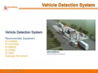
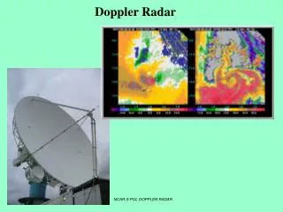
International Journal of Trend in Scientific Research and Development (IJTSRD) Volume 3 Issue 5, August 2019 Available Online: www.ijtsrd.com e-ISSN: 2456 – 6470 Implementation of Doppler Radar-Based Vehicle Speed Detection System May Zin Tun1, Kay Thwe Zin2 1Lecturer, Department of Electronic Engineering, Technological University, Mandalay, Myanmar 2Lecturer, Department of Electrical Engineering, Technological University, Mawlamyine, Myanmar How to cite this paper: May Zin Tun | Kay Thwe Zin "Implementation of Doppler Radar-Based Vehicle Speed Detection System" Published in International Journal of Trend in Scientific Research and Development (ijtsrd), ISSN: 2456- 6470, Volume-3 | Issue-5, August 2019, https://doi.org/10.31142/ijtsrd26653 Copyright © 2019 by author(s) and International Journal of Trend in Scientific Research and Development Journal. This is an Open Access article distributed under the terms of the Creative Commons Attribution License (CC (http://creativecommons.org/licenses/by /4.0) INTRODUCTION The most unwanted thing to happen to a road user is road accident. Most of the fatal accident occurs due to over speeding. Faster vehicles are easier to accident than the slower one. There is a wide range of technologies available for vehicle speed detectors. Some of the most common and some developing technologies are using video image processors, using ultrasonic detectors and using microwave radar. Among the various methods for detecting speed of the vehicle, object detection system based on Radar have been replaced for about century for various purposes like detection of aircrafts, spacecraft, ships and reading weather information. The essential feature in adaptive vehicle activated sign systems is the accurate measurement of a vehicle’s velocity. The velocities of vehicles are acquired form continuous wave Doppler radar. A very low amount of power is consumed in this system and only battery can use to operate. The system works on the principle of Doppler Effect by detecting the Doppler shift in microwaves reflected from a moving object. The receive Doppler shift by the Doppler radar is directly proportional to the speed of the object. Since, the output of the sensor is sinusoidal wave ABSTRACT Nowadays, vehicular accidents have been increasing from day to day. Most of them are the cause of over speeding. This thesis describes the Arduino based vehicle speed detection system using Doppler radar. The primary goal of this system is to design of the vehicle speed detector using Doppler radar which is used to reduce the amount of accidents caused by over speeding. In this system, continuous wave (CW) Doppler radar which is a special case that only provides a velocity output is used as a sensor and the microcontroller is used to calculate the speed of the vehicle. Moreover, the amplifier is used to amplify the voltage level to drive the microcontroller as the sensor output is in micro volts. It is also included LCD display to indicate the speed level. A Doppler radar that can determine the frequency shift that occurs in electromagnetic waves due to the motion of scatters toward or away from the observer through measurement of the phase change that occurs in electromagnetic waves during a series of pulses. The Doppler frequency is negative for objects receding from the radar. The Doppler frequency is positive for objects approaching the radar. This system can be acceptable in real-time applications because it is independent of temperature, humidity, noise airflow, dust, light, etc. The results of design are tested and follow through realization. Each of the implementation is evaluated and these evaluations lead to the conclusion that the design is able to achieve high accuracy of the speed. The major components of the design are Doppler radar (HB100), Arduino Uno, LCD display and LM324. C++ programming language is developed in this system. The results of this work can improve the performance of automobile safety system. KEYWORDS: Doppler radar (HB100); Arduino Uno; LCD display and LM324; C++ programming language with very small amplitude and needs to be amplified with the help of the amplifier before further processing. The purposed to calculate and display the speed on LCD is performed by microcontroller. This proposed system deals with one the efficient methods to provide safety to road users. Operation of Overall Proposed System The speed detection system can be simply divided into two main categories: the amplifier circuit and the frequency counter for speed display. The proposed block diagram for the Doppler radar-based vehicle speed detection system is shown in figure1.The speed detection system will manage the speed limit of a vehicle on road. This system will compose of Doppler radar, voltage regulator circuit, amplifier circuit and a main Arduino Uno. The Doppler radar operates by radiating electromagnetic waves and detecting the echo returned from the target. Although radar cannot resolve the detailed features of target like the human eyes, it can see through darkness, fog and rain, and over a much longer range. IJTSRD26653 pp.1708-1713, BY 4.0) @ IJTSRD | Unique Paper ID – IJTSRD26653 | Volume – 3 | Issue – 5 | July - August 2019 Page 1708
International Journal of Trend in Scientific Research and Development (IJTSRD) @ www.ijtsrd.com eISSN: 2456-6470 Figure1.Overall Block Diagram of Doppler Radar-based Vehicle Speed Detection System The vehicle speed is acquired from a continuous wave Doppler radar. It can detect motion or speed or speed of moving objects through Doppler Effect. The chosen radar for this system is HB100 whose transmitted frequency is 10.525GHz.The radar module operates at a+5Vdc for continuous wave(CW) operation.Consequently,+12V battery is used as the power supply by converting it to +5V via the voltage regulator using LM7805.The output of the 12V to 5V voltage regulator circuit is connected to +5V pin of the module. There are three main terminal in this module, +5V pinged (ground) pin and IF (intermediate frequency) pin. After applying the power supply to the radar module, the system starts working. The module sends its transmitted signal from the transmitting antenna to the vehicle. Then, the reflected signal is back to the receiving antenna with a shift in the frequency. The difference between the transmitted and received signal is known as the Doppler shift. The microcontroller operates only if its supply voltage is 3.5V at least. Therefore, a high gain low frequency amplifier is usually connected to the IF terminal in order to amplify the Doppler shift. The output of the amplifier is fed to the microcontroller. The purpose of the microcontroller is to calculate the speed of the vehicle via its frequency which is the major factor representing the speed of the vehicle. After performing the task of the calculating the speed of the vehicle, the LCD display is used to indicate the vehicle speed to the driver to know his speed is in over speed or not. Circuit Diagram of Doppler Radar-based Vehicle Speed Detection System The Doppler Radar-based Vehicle Speed Detection System uses Doppler Radar (HB100) to transmit to the motion and receive pulse to amplify output. The two LM324 amplifiers are connected to use for amplify and avoid the noises. The amplifier output is fed to the microcontroller. A microcontroller of Arduino Uno family is used to achieve the desired operation. Figure2. Circuit Diagram of Doppler Radar-based Vehicle Speed Detection System @ IJTSRD | Unique Paper ID – IJTSRD26653 | Volume – 3 | Issue – 5 | July - August 2019 Page 1709
International Journal of Trend in Scientific Research and Development (IJTSRD) @ www.ijtsrd.com eISSN: 2456-6470 And then, the LCD and buzzer are connected to the microcontroller. When the system is going on, the Doppler Radar (HB100) send pulse to the target and the pulse is hit the target and returned to the radar. The radar receives the pulse and converts to the frequency wave. But, the output of the frequency very low. So, we have to use the amplifier to amplify the frequency and avoid the noises. And then, the output is fed to the microcontroller. The microcontroller calculated the speed and display on the LCD. The circuit diagram of Doppler radar-based vehicle speed detection system is shown in figure 2. Flow Chart of the Doppler Radar-based Vehicle Speed Detection System test, experimental test and surveying test. Simulation test can be done by Proteus 8 Professional software. Experimental test and surveying test are done by the hardware construction. In this chapter, the Doppler radar cannot test by simulation as it is not contained in the device selection. It can only test by hardware device. Therefore, simulation test for amplifier circuit, experimental test for Doppler radar, amplifier circuit, and surveying result for the whole system are presented in this paper. The simulation testing for the amplifier circuit can be done by using Proteus 8 Professional Software before constructing the hardware whether the result is good or not. A. Simulation Results for Amplifier Circuit While choosing the IC for amplifier circuit, the system first selects two types of IC which are LM358N and LM324N. Both types are tested in Proteus software to know which result is better to use. The microcontroller needs to give the power supply of 3.5V at least. According to the simulation result shown in Figure 5 LM358N cannot amplify the voltage up to 3.5V. It can only amplify 3V and the output voltage is not the pure DC voltage. Using LM324, the amplifier circuit can amplify the voltage to 4Vdc as shown in Figure 7. Therefore, the system chooses to use LM324 for the purpose of amplifying the Doppler shift. The output of the Doppler radar is Doppler shift which is in micro volts. Therefore, the amplifier circuit using LM324N is used in the vehicle speed detection system based on Doppler radar. Testing and result the simulation of amplifier circuit using LM358N is shown in figure 4 and figure 5. Figure4. Testing the Simulation of Amplifier Circuit Using LM358N Figure3. Flow Chart of the Doppler Radar-based Vehicle Speed Detection System This flow chat is used from start. Initializing the input port and output port, the system is activated. In the first step, the Doppler radar is sensed the motion and transmit the pulse and reflect back from the target. In the second step, the pulse is converted pulse from frequency counter to as a speed. If the speed is detected, the microcontroller IC calculated and the speed is display on the LCD. And the next step, the calculated speed is over the assigned limit, the buzzer will make the noise. The flow chart of the Doppler radar-based vehicle speed detection system is shown in figure 3. Test and Results This paper describes the test and results of the proposed system. The test can be divided in three sections: simulation Figure5. Simulation Result of Amplifier Circuit Using LM358N Testing and result the simulation of amplifier circuit using LM324N is shown in figure 6 and figure 7. @ IJTSRD | Unique Paper ID – IJTSRD26653 | Volume – 3 | Issue – 5 | July - August 2019 Page 1710
International Journal of Trend in Scientific Research and Development (IJTSRD) @ www.ijtsrd.com eISSN: 2456-6470 Likewise, the output of the amplifier circuit occurs more oscillation in fast motion than in slow motion. C. Experimental Testing for Doppler Radar (HB100) and Arduino Uno Figure 10 and Figure 11 show the constructed hardware circuit from top view and front view. When the system is turned on, the power on Arduino board system is turn on. The Doppler radar detect the motion to transmit the pulse and receive the pulse. And then convert the pulse to frequency and form as a speed. Finally, display the speed results on the LCD. Figure6. Testing the Simulation of Amplifier Circuit Using LM324N Figure 10 Construct Hardware Circuit (Top View) Figure7. Simulation Result of Amplifier Circuit Using LM324N B. Testing the Output of the Doppler radar with Oscillator The Doppler radar cannot be tested in Proteus software. So, the output of the Doppler radar module is tested by hardware component and oscilloscope. By testing with oscilloscope, it can be known that the output waveforms are changed according to the rate of motion of the target. The amplitude of the output waveform in fast motion occurs more oscillation than that of the output waveform in slow motion. The experimental results of the Doppler radar are shown below. Figure 11 Overall Hardware Circuit (Front View) D. Surveying, Experimental Test and Results for Complete Constructed Circuit After constructing the whole circuit, the system needs to survey on the road shown in Figure 12. The results are changed according to the height of the pole that radar placed (h), the distance to the oncoming lane (d), and the angle that the radar must be titled (0). The cosine of the angle between the radar device and its target determines the magnitude of the error which is known as the cosine error and it becomes significant when the angle to the roadway is large. The greater the angle between the radar and the roadway, the lower is the indicated velocity. Figure8. Testing the Output Waveform of the Doppler radar Figure9. Result Output Waveform of the Doppler radar @ IJTSRD | Unique Paper ID – IJTSRD26653 | Volume – 3 | Issue – 5 | July - August 2019 Page 1711
International Journal of Trend in Scientific Research and Development (IJTSRD) @ www.ijtsrd.com eISSN: 2456-6470 To get the better result, the surveying on the road was done again and again with different parameters. At first, the target’s velocity was measured by placing the radar device on the ground beside the road. At the time, the error percentage for both car and cycle are very large. Therefore, the radar was placed at different heights and different angles to get the result which is nearly equal to the actual velocity. Figure 15 Testing the Speed of the Vehicle (Over) Figure 12 Surveying the Constructed Complete Circuit on the Road E. Test and Results of the Vehicle’ Speed Figure 13 to Figure 4.16 shows the tests and results of the vehicle’s speed. If the vehicle’s speed is over the assigned limit, its speed will show on the LCD and display the result over. If the speed is low the assigned limit, its speed will show on the LCD and display the result pass. Figure 16 Results of the Speed of the Vehicle Discussions In this system, a low cost and efficient embedded vehicular speed detecting system is presented. The work aimed at implementing the better results by comparing the existing methods such as FFT, DSP and LASAR based techniques. The output was more accurate with no other moving objects in the surrounding. In reality, the radar will not measure the actual velocity when the vehicle is not travelling directly towards the radar and slightly inclined at an angle. The measured velocity calculated from the frequency counter is different from the actual velocity displayed on the speedometer according to the cosine error. Although it is said that the sensor can detect in 20m range in the data sheet, it works well for the vehicle at a close range of about 7m. When the radar is placed at the height of about 2.25m, the result is more accurate for car. Otherwise, the result is more accurate for cycle when the radar is placed at the height of about 1.5m. The output was more accurate with no other moving objects in the surrounding. Sometimes, the sensor does not work well and cannot display the speed on LCD. Conclusion This system mainly composes of the amplifier circuit, Doppler radar (HB100), Arduino Uno, microcontroller ATmega328 and LCD display. The amplifier circuit is used to amplify the output of the Doppler radar as it is small dc value which cannot be fed directly to a microcontroller. The information about the target range, direction and velocity are provided by the nature of the returned signal of the Doppler radar. By keeping track of the time it takes the radio waves to leave the antenna, hit the target, and return to the Figure 13 Testing the Speed of the Vehicle (Pass) Figure 14 Results of the Speed of the Vehicle @ IJTSRD | Unique Paper ID – IJTSRD26653 | Volume – 3 | Issue – 5 | July - August 2019 Page 1712
International Journal of Trend in Scientific Research and Development (IJTSRD) @ www.ijtsrd.com eISSN: 2456-6470 [5]Mohammed, A., Ahmed, A., and Mohammed, B.: Radar Vehicle Detector Mode, International Journal of Enhanced Research in Science Technology & Engineering. 2(3) March (2013) ISSN: 2319-7463. antenna, the radar can calculate the distance to the target. By measuring the shift in phase between a transmitted pulse and a received echo, the target’s radial velocity can be calculated. If the radar was placed directly in front of the car, the car speed would be very close to the actual speed. If the reflecting object is located from the centerline of the radar beam, the lower the estimate of car speed. The microcontroller performs the task of calculation of frequency and speed. After calculating the frequency and speed, the information is indicated on the LCD display References [1]Sairaj, B., Mayuresh, S., and Bhusan., T.: Survey of Various Methods used for Speed Calculation of a Vehicle, (2010). [6]Asha, G., H., Udayshankar, R., and Rashmi, N.: Radar Based Cost Effective Vehicle Speed Detection Using Zero Cross Detection, International Journal of Electrical, Electronics and Data Communication, 1(9) November (2013) ISSN: 2320-2084. [7]Mohammad, A., Bara, S., and Hasan, K.: Target Tracking Using Doppler Radar, (2014). [8]Diala. J., Siril, Y., and Mark, D.; Data Based Calibration System for Radar Used by Vehicle Activated Signs, Journal of Data Analysis and Information Processing. ISSN: 106-116, November (2014). [2]Lamis, I., A., Z.: Radar System Design, August (2011). [3]Thomas, L., F.: Electronic Devices: Ninth Edition, (2012). [9]Amit, S.., Abhishek, T.; Low Cost X-Band Radar System for Multiple Target Detection, International Journal of Research in Engineering Technology, 4(3) May (2015). [4]Anonymous, Typical Doppler Signal Amplifier, April (2012). [10]Agilsense.: HB100 Microwave Sensor Application Note, MSAN-001, ST Engineering Co. Ltd (2016). @ IJTSRD | Unique Paper ID – IJTSRD26653 | Volume – 3 | Issue – 5 | July - August 2019 Page 1713