Download
1 / 4
40 likes | 42 Views
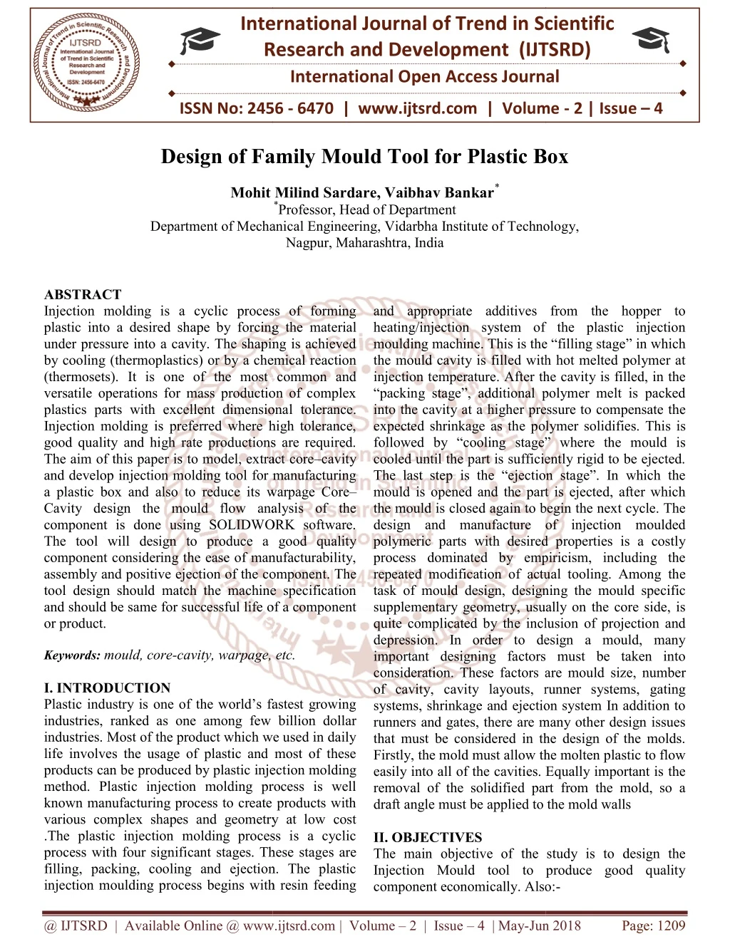
Injection molding is a cyclic process of forming plastic into a desired shape by forcing the material under pressure into a cavity. The shaping is achieved by cooling thermoplastics or by a chemical reaction thermosets . It is one of the most common and versatile operations for mass production of complex plastics parts with excellent dimensional tolerance. Injection molding is preferred where high tolerance, good quality and high rate productions are required. The aim of this paper is to model, extract corecavity and develop injection molding tool for manufacturing a plastic box and also to reduce its warpage CoreCavity design the mould flow analysis of the component is done using SOLIDWORK software. The tool will design to produce a good quality component considering the ease of manufacturability, assembly and positive ejection of the component. The tool design should match the machine specification and should be same for successful life of a component or product. Mohit Milind Sardare | Vaibhav Bankar "Design of Family Mould Tool for Plastic Box" Published in International Journal of Trend in Scientific Research and Development (ijtsrd), ISSN: 2456-6470, Volume-2 | Issue-4 , June 2018, URL: https://www.ijtsrd.com/papers/ijtsrd14245.pdf Paper URL: http://www.ijtsrd.com/engineering/mechanical-engineering/14245/design-of-family-mould-tool-for-plastic-box/mohit-milind-sardare<br>

E N D
International Research Research and Development (IJTSRD) International Open Access Journal International Open Access Journal International Journal of Trend in Scientific Scientific (IJTSRD) ISSN No: 2456 - 6470 | www.ijtsrd.com | Volume ISSN No: 2456 6470 | www.ijtsrd.com | Volume - 2 | Issue – 4 Design of Family Mould Tool for Plastic Box Design of Family Mould Tool for Plastic Box Design of Family Mould Tool for Plastic Box Milind Sardare, Vaibhav Bankar* *Professor, Head of Department Mohit Department of Mechanical Engineering tment of Mechanical Engineering, Vidarbha Institute of Technology Nagpur, Maharashtra, India f Technology, and appropriate additives from the hopper to heating/injection system of the plastic injection moulding machine. This is the “filling stage the mould cavity is filled with hot melted polymer at injection temperature. After the cavity is filled, in the “packing stage”, additional polymer melt is packed into the cavity at a higher pressure to compensate the expected shrinkage as the polymer solidifies. This is followed by “cooling stage” where the mould is cooled until the part is sufficiently rigid to be ejected. The last step is the “ejection stage”. In which the mould is opened and the part is ejected, after which the mould is closed again to begin the next cycle. The design and manufacture of injection moulded polymeric parts with desired properties is a costly process dominated by empiricism, including the repeated modification of actual tooling. Among the task of mould design, designing the mould specific supplementary geometry, usually on the core side, is quite complicated by the inclusion of projection and depression. In order to design a mould, many important designing factors must be taken into consideration. These factors are of cavity, cavity layouts, runner systems, gating systems, shrinkage and ejection system In addition to runners and gates, there are many other design issues that must be considered in the design of the molds. Firstly, the mold must allow the molten plastic to flow easily into all of the cavities. Equally important is the removal of the solidified part from the mold, so a draft angle must be applied to the mold walls II. OBJECTIVES The main objective of the study is to design the Injection Mould tool to produce good quality component economically. Also: component economically. Also:- ABSTRACT Injection molding is a cyclic process of forming plastic into a desired shape by forcing the under pressure into a cavity. The shaping is achieved by cooling (thermoplastics) or by a chemical reaction (thermosets). It is one of the most common and versatile operations for mass production of complex plastics parts with excellent dimensiona Injection molding is preferred where high tolerance, good quality and high rate productions are required. The aim of this paper is to model, extract core and develop injection molding tool for manufacturing a plastic box and also to reduce its warpage Core Cavity design the mould flow analysis of the component is done using SOLIDWORK software. The tool will design to produce a good quality component considering the ease of manufacturability, assembly and positive ejection of the componen tool design should match the machine specification and should be same for successful life of a component or product. Keywords: mould, core-cavity, warpage, etc. I. INTRODUCTION Plastic industry is one of the world’s fastest growing industries, ranked as one among few billion dollar industries. Most of the product which we used in daily life involves the usage of plastic and most of these products can be produced by plastic inject method. Plastic injection molding process is well known manufacturing process to create products with various complex shapes and geometry at low cost .The plastic injection molding process is a cyclic process with four significant stages. These filling, packing, cooling and ejection. The plastic injection moulding process begins with resin feeding injection moulding process begins with resin feeding Injection molding is a cyclic process of forming plastic into a desired shape by forcing the material under pressure into a cavity. The shaping is achieved by cooling (thermoplastics) or by a chemical reaction (thermosets). It is one of the most common and versatile operations for mass production of complex plastics parts with excellent dimensional tolerance. Injection molding is preferred where high tolerance, good quality and high rate productions are required. The aim of this paper is to model, extract core–cavity and develop injection molding tool for manufacturing and appropriate additives from the hopper to heating/injection system of the plastic injection moulding machine. This is the “filling stage” in which the mould cavity is filled with hot melted polymer at injection temperature. After the cavity is filled, in the “packing stage”, additional polymer melt is packed into the cavity at a higher pressure to compensate the olymer solidifies. This is followed by “cooling stage” where the mould is cooled until the part is sufficiently rigid to be ejected. The last step is the “ejection stage”. In which the mould is opened and the part is ejected, after which d again to begin the next cycle. The design and manufacture of injection moulded polymeric parts with desired properties is a costly process dominated by empiricism, including the repeated modification of actual tooling. Among the igning the mould specific supplementary geometry, usually on the core side, is quite complicated by the inclusion of projection and depression. In order to design a mould, many important designing factors must be taken into consideration. These factors are mould size, number of cavity, cavity layouts, runner systems, gating systems, shrinkage and ejection system In addition to runners and gates, there are many other design issues that must be considered in the design of the molds. ow the molten plastic to flow easily into all of the cavities. Equally important is the removal of the solidified part from the mold, so a draft angle must be applied to the mold walls uce its warpage Core– Cavity design the mould flow analysis of the component is done using SOLIDWORK software. The tool will design to produce a good quality component considering the ease of manufacturability, assembly and positive ejection of the component. The tool design should match the machine specification for successful life of a component cavity, warpage, etc. Plastic industry is one of the world’s fastest growing industries, ranked as one among few billion dollar industries. Most of the product which we used in daily life involves the usage of plastic and most of these products can be produced by plastic injection molding method. Plastic injection molding process is well known manufacturing process to create products with various complex shapes and geometry at low cost .The plastic injection molding process is a cyclic process with four significant stages. These stages are filling, packing, cooling and ejection. The plastic The main objective of the study is to design the Injection Mould tool to produce good quality @ IJTSRD | Available Online @ www.ijtsrd.com @ IJTSRD | Available Online @ www.ijtsrd.com | Volume – 2 | Issue – 4 | May-Jun 2018 Jun 2018 Page: 1209
International Journal of Trend in Scientific Research and Development (IJTSRD) ISSN: 2456-6470 To design the family mould. To provide hinge to box and lid. To improve interlocking between box and lid. To reduce Injection moulding cycle time. To reduce the warpage occurrence. Make conceptual design of mould. Design calculations. III. MODEL STUDY AND MODELLING OF COMPONENT Model study includes identifying the criticality in component, following are the criticality involved in component Proper ejection method required to eject the component. Bosses at the sides needs to proper placement of screw inserts. Component is modeled SOLIDWORK Component has a rectangular structure with dimensions: 125mm (length), 99 mm (width), 37.5 mm (height)mm. Also component got one rectangular covering, and ribs at sides shown in the figure.2. Other details of model are given below Component name: plastic box Component material: PP (polypropylene ) Shrinkage : 1.5 Moulding type: single Cavity injection mould tool Projected Surface area = 85235.63 Sq. mm(From CAD model).The injection temperature, time and pressure were 2300C, 13.56 Sec and 150 MPa, respectivelyare obtained by simulation technique. Fig. 1 shows the 3D model of plastic box Three design concepts had been considered in designing of the mould including: i. Three-plate mould (Concept 1) having two parting line with single cavity. Not applicable due to high cost and complicated profile of component. ii. Two-plate mould (Concept 2) having one parting line with double cavities with gating and ejection system. Not applicable because complexity in designing. iii. Two-plate mould (Concept 3) having one parting line with single cavity without gating system. While designing of the mould third concept had been applied. Initially, the mould was designed based on the platen dimension of the plastic injection machine used. There was a limitation of the machine, which is the maximum area of machine platen and is given by the distance between two tiebars. Therefore, the maximum width of the mould plate should not exceed this distance. Basically, core and cavity extraction was done on the basis of the criticality of the component, after core-cavity extraction from specified modeling software, mold base also modeled on the same software, finally core cavity inserts are assembled into the mold base. Design calculation Numeric calculation to be carried out to predict the weight of the component, Shot Capacity, Plasticizing Capacity ,Clamping Capacity , on which machine mold to be loaded, plasticizing and shot capacity of the machine, and cooling parameters like inlet and outlet temperature effect, weight of water to be circulate. these results are compared with the simulation results during moulding. using the software . Data from CAD model Surface area = 85235.63 Sq. mm Material = Polypropylene Mass = 42.02 grams QB = 546 KJ/Kg Figure No. 1 3D model of plastic box. Density = 0.9 kg/dm3 IV. DESIGN OF MOULD This section describes the design aspects and other considerations involved in designing the mould to produce plastic box. Moulding Temp = 250 0C Calculation of Number Cavities Based on:- @ IJTSRD | Available Online @ www.ijtsrd.com | Volume – 2 | Issue – 4 | May-Jun 2018 Page: 1210
International Journal of Trend in Scientific Research and Development (IJTSRD) ISSN: 2456-6470 1.Shot Capacity Np= 1.03≈ 1 Ns=?.??×? ? 3.Clamping Capacity Pc × Am Where, c = Rated Clamping Capacity = 800 KN Am = Projected area of moulding including runner and sprue Pc = Cavity Pressure Approx. = 63 Mpa. 800 × 10? 63 × 10?× 85235.63 × 10?? Nc = 0.14 ≈ 1 Assume. Where, c Nc = Ns : Number of cavities based on shot capacity M :- Mass of component. W: - shot capacity for polymer W = Sv × ρ × C ?? = Sv: - Swept Volume C: - Constant ρ :- Density of material. Sv= 100 cm2 W= 100 ×0.9×0.93 W = 83.7 gm. Ns =0.85 × W M ?? =0.875 × 83.9 42.02 Ns =1.69 ≈2 2.Plasticizing Capacity Np =0.85 × P × Tc 3600 × M Where, Np:- Number of Cavities Based on Plasticizing Capacity. Tc = cycle time Tc=?×???? ?? M = Mass = 42.02 gram. Ps :- Plasticizing Capacity of Machine Determination of number of cavity From the above calculation of component and its shape and size one cavity moulds is preferred. V. TOOL ASSEMBLY Tool assembly is done in modeling software, includes the fixing of extracted core and cavity inserts into the mould base, after assembly 3D models are converted into the 2D drawings for manufacturing process. = 40 kg/hr Tc=??.??×???? ??×???? Tc = 10.50 second. QA- Total Heat Content Of Polystyrene. QB- Total Heat Content Of Material Actual to be used. P=??×?? P=??×???.? ??? P = 17.538 Kg/hr. Np =0.85 × P × Tc 3600 × M Np=?.??×??.???×??.?×???? ????×??.?? Figure No. 2 Core Cavity Extraction (Expolded view) ?? Figure No.3 Assembly of Mould Tool @ IJTSRD | Available Online @ www.ijtsrd.com | Volume – 2 | Issue – 4 | May-Jun 2018 Page: 1211
International Journal of Trend in Scientific Research and Development (IJTSRD) ISSN: 2456-6470 REFRENCES 1)A book on “All About Plastics” by N I George. 2)A book on “Injection mould design” by R.G.W. 3)HASCO Standard. 4)Madhukumar, Kumarswamy , “Design of plastic injection mould tool for air Filter box bottom cover”, International Journal Of Modern Trends In Engineering and research Volume 02, Issue 04, [April – 2015]. Sampathkumar, Nataraj, Figure No.4 3D modeling of Mould Assembly 5)Jian ZHOU , Lijun LI , Yihua HU ,Jianguo YANG, K CHENG “Plastic mold design of top- cover of out-shell of mouse based on CAE”, International Journal Of Advanced In Control Engineering And Information Science, 2011. 6)PravinShinde, S. S. Patil, Swapnil S. Kulkarni, “Design And Development Of Plastic Injection Mold for Auto Component”, International Journal of Scientific Research and Management Studies (IJSRMS) Volume 2 Issue 3. 7)B.IftekharHussain, Mir Safiulla, Mohamed Ali, G.Suresh, "Injection Mould Tool Design of Power Box Side Panel", International Journal of Innovative Research in Science, Engineering and Technology, Vol. 3, Issue 2, February 2014. 8)NikMizamzulMehat, ShahrulKamaruddin, and Abdul Rahim Othman, "Modeling and Analysis of Injection Moulding Process Parameters for Plastic Gear Industry Application”, Hindawi Publishing Corporation Engineering Volume 2013, Article ID 869736. Figure No. 5 Expolded view of Assembly IV. CONCLUSION In this project, we carried out the Design and Analysis of Family Mould for Plastic Box.The complete injection mould tool is designed for fabricating plastic box by using solid work. The plastic flow analysis is carried out using solid work. All the results viz. fill time, temperature at the end of fill, weld lines, air traps, Ease of fill prediction are analysed and also we have design the mould tool assembly for plastic box by considering standard design consideration and it has not shown any error in the mould flow analysis. ISRN Industrial 9)Jithin k1, Kannakumar k2, "Process Parameter Optimization of Injection Concurrent Approach”, IJISET - International Journal of Innovative Science, Engineering & Technology, Vol. 3 Issue 12, December 2016. Mold Using 10)Vijaykumar Vilas Andhalka, Dr. S. R. Dulange, "Injection molding methods design, optimization, Simulation of plastic flow reducer part by mold flow analysis”, International Research Journal of Engineering and Technology (IRJET)Volume: 04 Issue: 06 | June -2017. @ IJTSRD | Available Online @ www.ijtsrd.com | Volume – 2 | Issue – 4 | May-Jun 2018 Page: 1212