Download
1 / 8
80 likes | 84 Views
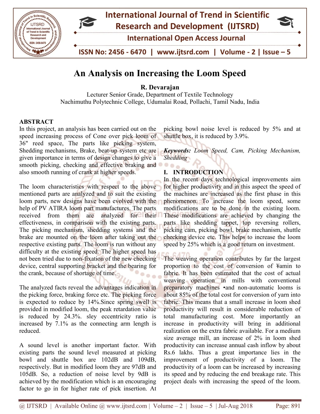
In this project, an analysis has been carried out on the speed increasing process of Cone over pick loom of 36 reed space, The parts like picking system, Shedding mechanisms, Brake, beat up system etc are given importance in terms of design changes to give a smooth picking, checking and effective braking and also smooth running of crank at higher speeds. The loom characteristics with respect to the above mentioned parts are analyzed and to suit the existing loom parts, new designs have been evolved with the help of PV ATIRA loom part manufactures. The parts received from them are analyzed for their effectiveness, in comparison with the existing parts. The picking mechanism, shedding systems and the brake are mounted on the loom after taking out the respective existing parts. The loom is run without any difficulty at the existing speed. The higher speed has not been tried due to non fixation of the new checking device, central supporting bracket and the bearing for the crank, because of shortage of time. The analyzed facts reveal the advantages indication in the picking force, braking force etc. The picking force is expected to reduce by 14 .Since spring swell is provided in modified loom, the peak retardation value is reduced by 24.3 . sley eccentricity ratio is increased by 7.1 as the connecting arm length is reduced. A sound level is another important factor. With existing parts the sound level measured at picking bowl and shuttle box are 102dB and 109dB, respectively. But in modified loom they are 97dB and 105dB. So, a reduction of noise level by 9dB is achieved by the modification which is an encouraging factor to go in for higher rate of pick insertion. At picking bowl noise level is reduced by 5 and at shuttle box, it is reduced by 3.9 . R. Devarajan "An Analysis on Increasing the Loom Speed" Published in International Journal of Trend in Scientific Research and Development (ijtsrd), ISSN: 2456-6470, Volume-2 | Issue-5 , August 2018, URL: https://www.ijtsrd.com/papers/ijtsrd15951.pdf Paper URL: http://www.ijtsrd.com/engineering/textile-engineering/15951/an-analysis-on-increasing-the-loom-speed/r-devarajan<br>

E N D
International Research Research and Development (IJTSRD) International Open Access Journal An Analysis on Increasing the Loom Speed R. Devarajan Senior Grade, Department of Textile Technology Nachimuthu Polytechnic College, Udumalai Road, Pollachi, Tamil Nadu Udumalai Road, Pollachi, Tamil Nadu, India International Journal of Trend in Scientific Scientific (IJTSRD) International Open Access Journal ISSN No: 2456 ISSN No: 2456 - 6470 | www.ijtsrd.com | Volume 6470 | www.ijtsrd.com | Volume - 2 | Issue – 5 An Analysis on Increasing t he Loom Speed Lecturer Senior Grade, De Nachimuthu Polytechnic College, picking bowl noise level is reduced by 5% and at shuttle box, it is reduced by 3.9%. Keywords: Loom Speed, Cam, Picking Mechanism, Shedding I. INTRODUCTION In the recent days technological improvements aim for higher productivity and in this aspect the speed of the machines are increased as the first phase in this phenomenon. To increase the loom speed, some modifications are to be done in the existing loom. These modifications are achieved by changing the parts like shedding tappet, top reversing rollers, picking cam, picking bowl, brake mechanism, shuttle checking device etc. This helps to increase the loom speed by 25% which is a good return on investment. The weaving operation contributes by far the largest proportion to the cost of conversion of ¥amin fabric. It has been estimated that the cost of actual weaving operation in mills with conventional preparatory machines •and non about 85% of the total cost for conversion of yarn into fabric. This means that a small increase in loom shed productivity will result in considerable reduction of total manufacturing cost. More importantly an increase in productivity will bring in additional realization on the extra fabric available. For a medium size average mill, an increase of 2% in loom shed productivity can increase annual cash inflow by about Rs.6 lakhs. Thus a great importance lies in the improvement of productivity of a loom. The productivity of a loom can be increased by increasing its speed and by reducing the end breakage rate. This project deals with increasing the speed of the loom. project deals with increasing the speed of the loom. ABSTRACT In this project, an analysis has been carried out on the speed increasing process of Cone over pick loom of 36" reed space, The parts like picking system, Shedding mechanisms, Brake, beat-up system etc are given importance in terms of design changes to give a smooth picking, checking and effective braking and also smooth running of crank at higher speeds. The loom characteristics with respect to the above mentioned parts are analyzed and to suit the existing loom parts, new designs have been evolved with the help of PV ATIRA loom part manufactures. The parts received from them are analyzed for their effectiveness, in comparison with the existing parts. The picking mechanism, shedding systems and the brake are mounted on the loom after taking out the respective existing parts. The loom is run without any difficulty at the existing speed. The higher speed has not been tried due to non-fixation of the new checking device, central supporting bracket and the bearing for the crank, because of shortage of time. The analyzed facts reveal the advantages indication in the picking force, braking force etc. The picking force is expected to reduce by 14%.Since spring swell is provided in modified loom, the peak retardation value is reduced by 24.3%. sley eccentricity ratio is increased by 7.1% as the connecting arm length is reduced. A sound level is another important factor. With existing parts the sound level measured at picking bowl and shuttle box are 102dB and 109dB, respectively. But in modified loom they are 97dB and 105dB. So, a reduction of noise level by 9dB is achieved by the modification which is an encouraging factor to go in for higher rate of pick insertion. At her rate of pick insertion. At In this project, an analysis has been carried out on the speed increasing process of Cone over pick loom of parts like picking system, picking bowl noise level is reduced by 5% and at shuttle box, it is reduced by 3.9%. up system etc are Loom Speed, Cam, Picking Mechanism, given importance in terms of design changes to give a smooth picking, checking and effective braking and also smooth running of crank at higher speeds. In the recent days technological improvements aim productivity and in this aspect the speed of the machines are increased as the first phase in this phenomenon. To increase the loom speed, some modifications are to be done in the existing loom. These modifications are achieved by changing the hedding tappet, top reversing rollers, picking cam, picking bowl, brake mechanism, shuttle checking device etc. This helps to increase the loom speed by 25% which is a good return on investment. with respect to the above mentioned parts are analyzed and to suit the existing loom parts, new designs have been evolved with the help of PV ATIRA loom part manufactures. The parts received from them are analyzed for their h the existing parts. The picking mechanism, shedding systems and the brake are mounted on the loom after taking out the respective existing parts. The loom is run without any difficulty at the existing speed. The higher speed has fixation of the new checking device, central supporting bracket and the bearing for The weaving operation contributes by far the largest ion to the cost of conversion of ¥amin to fabric. It has been estimated that the cost of actual weaving operation in mills with conventional preparatory machines •and non-automatic looms is about 85% of the total cost for conversion of yarn into is means that a small increase in loom shed productivity will result in considerable reduction of total manufacturing cost. More importantly an increase in productivity will bring in additional realization on the extra fabric available. For a medium verage mill, an increase of 2% in loom shed productivity can increase annual cash inflow by about Rs.6 lakhs. Thus a great importance lies in the improvement of productivity of a loom. The productivity of a loom can be increased by increasing by reducing the end breakage rate. This The analyzed facts reveal the advantages indication in the picking force, braking force etc. The picking force ce by 14%.Since spring swell is provided in modified loom, the peak retardation value is reduced by 24.3%. sley eccentricity ratio is increased by 7.1% as the connecting arm length is A sound level is another important factor. With the sound level measured at picking bowl and shuttle box are 102dB and 109dB, respectively. But in modified loom they are 97dB and 105dB. So, a reduction of noise level by 9dB is achieved by the modification which is an encouraging @ IJTSRD | Available Online @ www.ijtsrd.com @ IJTSRD | Available Online @ www.ijtsrd.com | Volume – 2 | Issue – 5 | Jul-Aug 2018 Aug 2018 Page: 891
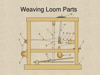
International Journal of Trend in Scientific Research and Development (IJTSRD) ISSN: 2456 International Journal of Trend in Scientific Research and Development (IJTSRD) ISSN: 2456 International Journal of Trend in Scientific Research and Development (IJTSRD) ISSN: 2456-6470 The picking shafts, a both sides are dismantled from the loom. The shedding cams at the center of the bottom shaft are loosened. The heads are disconnected from the treadle lever and tied separately. The picking noses are removed from both sides of the bottom shaft. The brackets at both sides of the shaft connected with the picking cams are loosened from them and the picking cams are loosened on the shaft. The weft fork cam is loosened from the shaft, The brackets at the center, supporting the bottom shaft from the frame are loosened. shaft from the frame are loosened. The modified loom parts, for this project are received from M/s. PoonjabhaiVanmali & Sons Ahmadabad. II. PLAN OF WORK For this Project, Based upon facts, the par shedding tappet, picking tappet, picking cam, bowl, top reversing roller, shuttle checking device, brake mechanism, motor and loom pulleys and fly wheel have been modified in terms of dimensions, design aspects, and working methods. With th modification. The modified loom parts, for this project are received The picking shafts, a both sides are dismantled & Sons Ahmadabad. The shedding cams at the center of the bottom For this Project, Based upon facts, the parts like picking tappet, picking cam, picking bowl, top reversing roller, shuttle checking device, brake mechanism, motor and loom pulleys and fly wheel have been modified in terms of dimensions, design aspects, and working methods. With the above The heads are disconnected from the treadle lever The picking noses are removed from both sides of The brackets at both sides of the shaft connected with the picking cams are loosened from them and icking cams are loosened on the shaft. The weft fork cam is loosened from the shaft, The brackets at the center, supporting the bottom Figure 1: Picking and Shedding Mechanism Figure 1: Picking and Shedding Mechanism The following works are carried out in the existing conventional non-automatic loom. The shedding and picking mechanism of the conventional loom are modified by using high speed shedding and picking cams, top reversion rollers and picking bowl. The conventional shoe brake is replaced by blued brake. Loom timings before and after modifications are checked. The displacement, velocity and acceleration diagrams of shuttle are drawn before and aft modifications. The noise level at the picking bowl and at shuttle box is increased for both before and after modifications. The speed, braking force and slay eccentricity before and after modifications are calculated. III. WORK PROCEDURES 3.1 Replacement of Mechanism The conventional end picking tappets are replacedby ATIRA high speed shedding and picking tappets are follows. The let-off weights are removed, and let is unwrapped from the weaver's beam. The weaver's beam is removed from the loom and placed on the floor by slowly unrolling the warp sheet. This makes it convenient to work under the loom. The following works are carried out in the existing The shedding and picking mechanism of the conventional loom are modified by using high picking cams, top reversion The conventional shoe brake is replaced by blued Loom timings before and after modifications are Figure 2: Components Figure 2: Components The brackets at both sides of the loom. Which keep the bottom shaft in position with the frame are loosened. At the drive side the gear wheel on the bottom shaft is take Neff the shaft. The bottom shaft is removed out of the loom. From the non-driving side and the cams collars and brackets are removed from it. The insertion of the various parts on the bottom shaft is done in the following sequence 1.The bracket connecting the picking cam with the bottom shaft is inserted up to the left and of the shaft. The key is inserted in the key way. 2.The weft fork cam is pushed shaft. 3.The collars connecting the bottom shaft with frame reinserted, 4.The collar connecting the picking cam with the bottom shaft at the high and is inserted over the shaft. The bottom shaft is mounted on loom. The bottom shaft is mounted on loom. The displacement, velocity and acceleration diagrams of shuttle are drawn before and after The brackets at both sides of the loom. Which shaft in position with the frame The noise level at the picking bowl and at shuttle box is increased for both before and after At the drive side the gear wheel on the bottom shaft is take Neff the shaft. The bottom shaft is removed out of the loom. driving side and the cams collars and brackets are removed from it. nsertion of the various parts on the bottom shaft is done in the following sequence The bracket connecting the picking cam with the bottom shaft is inserted up to the left and of the shaft. The key is inserted in the key way. The weft fork cam is pushed over the bottom The speed, braking force and slay eccentricity before and after modifications are calculated. Replacement of Shedding Shedding & & Picking Picking The conventional end picking tappets are replacedby ATIRA high speed shedding and picking tappets are off weights are removed, and let-off chain is unwrapped from the weaver's beam. The beam is removed from the loom and placed on the floor by slowly unrolling the warp sheet. This makes it convenient to work under the The collars connecting the bottom shaft with The collar connecting the picking cam with the bottom shaft at the high and is inserted over the @ IJTSRD | Available Online @ www.ijtsrd.com @ IJTSRD | Available Online @ www.ijtsrd.com | Volume – 2 | Issue – 5 | Jul-Aug 2018 Aug 2018 Page: 892
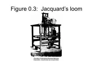
International Journal of Trend in Scientific Research and Development (IJTSRD) ISSN: 2456 International Journal of Trend in Scientific Research and Development (IJTSRD) ISSN: 2456 International Journal of Trend in Scientific Research and Development (IJTSRD) ISSN: 2456-6470 The outside brackets at both sides of the bottom shafts are bolted to the frame in order t6 keep the shaft in position at any time. The split type picking cams fixed on the shaft on both aside. They are firmly bolted to their brackets. The split type shedding cams are fitted on the bottom shaft that their profiles are in touch with the treadle bowls. The head shafts are untied end connected to the treadle lever. The gear wheel is mounted on the bottom shaft at the driving side. The picking nose is fitted with the cam sides. The picking abstained are fitted at both sides of the loom. The picking nose and the picking cone are checked for proper surface contact between them. The top reversing rollers along with the Doll head roller pipe. at the top of the loom are replaced by a larger pipe with larger rollers. The straps from the head shafts are top reversing rollers. The loom is set for proper timing. Thus the shedding and picking mechanisms are replaced in a conventional loom. 3.1.1 Replacement of Brake The shoe brake of the conventional loom is replaced by a band brake. This is done in the following manner. Replacement of shoe brake: The existing shoe brake can be replaced with the band brake. It is fluted to the loom with the help of the An that is us•1,d to fit the shoe brake. The other and of the band brake is connected to the) rake lever. At this, point, the band should be perpendicular to the ground. If it is inclined towards the brake-wheel, one brake will apply continuously. If it is inclined outwa loom will not step within half revolution of the crank shaft, after the application of the brake. Setting the band brake: A.When the starting handle is in the OFD' position, the distance between the brake hook and the brake lever should be 1/8". The brake is tightened in this position. B.When the starting handle is moved to the on.) Position, the brake-off tongue in the starting handle should lift the inclined lever by 3/6". sides of the bottom 3.2 Picking Cam The profiles of the ordinary as well as ATIRA High speed picking tappets have been drawn with the figure obtained by superimposing the two profiles, the following changes have to be - 1.The sheO1 or the base of the ATIRA picking cam has a higher diameter compared to normal picking cam. 2.More duration of crankshaft rotation is provided for accelerating & picking the shuttle. In ordinary picking cam, the duration for accelerating picking = 70' crankshaft rotation. In the modified cam, a longer nose bit is given. Compared to normal picking cam. The other measurements made before and after modification. shafts are bolted to the frame in order t6 keep the The profiles of the ordinary as well as ATIRA High- speed picking tappets have been drawn with the figure obtained by superimposing the two profiles, the The split type picking cams fixed on the shaft on both aside. They are firmly bolted to their -n noted. The split type shedding cams are fitted on the ttom shaft that their profiles are in touch with The sheO1 or the base of the ATIRA picking cam has a higher diameter compared to normal picking shafts are untied end connected to the More duration of crankshaft rotation is provided for accelerating & picking the shuttle. The gear wheel is mounted on the bottom shaft at In ordinary picking cam, the duration for accelerating cking = 70' crankshaft rotation. In the modified cam, a longer nose bit is given. Compared to normal picking cam. The other measurements made before The picking nose is fitted with the cam at both picking abstained are fitted at both sides of The picking nose and the picking cone are contact between them. The top reversing rollers along with the Doll head the top of the loom are replaced by a The straps from the head shafts are bolted to the Figure 3: Profile of Pickling Tappets Figure 3: Profile of Pickling Tappets Thus the shedding and picking mechanisms are Shuttle checking devices In modified high speed loom, spring swell is used. swell is made up 6f spring steel bent in a loop. So that it provides frictional surface to the shuttle and spring pressure. In this type of swell, there are multiple impacts with shuttle during checking. In this type of swell, the checking of shuttle is smoother. the time taken is more. The peak retardation value is low in 'Widen spring swell. 3.3 Shuttle checking devices In modified high speed loom, spring swell is Spring swell is made up 6f spring steel bent in a loop. So that it provides frictional surface to the shuttle and spring pressure. In this type of swell, there are multiple impacts with shuttle during this type of swell, the checking of shuttle is However the time taken is more. The peak retardation value is low in 'Widen spring swell. A spring type of swell which is used in modified loom consists of a wooden block. At the back of wooden block there is a leather strap. The shuttle box is also modified to incorporate floating swell. This swell is also provided with an easing mechanism. In the modified loom, the dimensions of shuttle box are Length of shuttle box = 540.mm Length of shuttle Length of pin= 370mm 3.4 Swell release mechanisms It consists of two levers which are kept as one assembly. These are rotating freely on extended sley sword pin. This receives oscillating motion from connecting arm through a pin. The assembly pulls the swell bracket assembly pulls the swell bracket for every picking. The shoe brake of the conventional loom is replaced by a band brake. This is done in the following manner. Replacement of shoe brake: The existing shoe brake can be replaced with the band brake. It is fluted to the loom with the help of the An that is ,d to fit the shoe brake. The other and of the band brake is connected to the) rake lever. At this, point, the band should be perpendicular to the ground. If it is A spring type of swell which is used in modified loom consists of a wooden block. At the back of the wooden block there is a leather strap. The shuttle box incorporate floating swell. This swell is also provided with an easing mechanism. In the modified loom, the dimensions of shuttle box are = 540.mm f shuttle Length of pin= 370mm wheel, one brake will apply continuously. If it is inclined outwards, the loom will not step within half revolution of the crank When the starting handle is in the OFD' position, the distance between the brake hook and the brake lever should be 1/8". The brake is tightened in this Swell release mechanisms It consists of two levers which are kept as one are rotating freely on extended sley sword pin. This receives oscillating motion from When the starting handle is moved to the on.) off tongue in the starting handle should lift the inclined lever by 3/6". pin. The oscillating lever @ IJTSRD | Available Online @ www.ijtsrd.com @ IJTSRD | Available Online @ www.ijtsrd.com | Volume – 2 | Issue – 5 | Jul-Aug 2018 Aug 2018 Page: 893
International Journal of Trend in Scientific Research and Development (IJTSRD) ISSN: 2456-6470 The extent and duration of pulling can be adjusted by adjusting the angle between11No levers and shifting the nylon roller mounted on the swell bracket. 3.5 Brake Analysis The shoe brake has been replaced by the band brake. The effective friction force applied on the brake wheel has-been calculated for the two brakes individually. The measurements such as weight of dead weight, length of levers, angle of wrap, length between fulcrum point and the pressure application, etc. have been made to calculate the effective friction force applied. 3.7 Loom Speed The speed of the conventional loom can be increased from 182 rpm to 226 rpm by increasing the diameter of the rotor pulley. There is a slight increase in the diameter of the loom pulley also. But the required high speed is achieved. 3.8 Noise Level Measurement The sound level has been measured at two different points in the loom, via picking bowl, and shuttle box. Before measuring, the following steps have been taken. 1.The shedding tappets are removed from the bottom shaft to avoid the noise due to shedding 2.The Heads are separated to the maximum distance and tied at their position. 3.The crank connecting arm is dismantled from the sley and the sley is kept tied at the front central mi.ke fitted to noise level meter is kept near the picking is kept near the picking bowl of the modified loom .First the noise level meter is adjusted and kept at 90dB and fluctuations of needle are noted. It showed 70dBs. Now the sound level measured in 97dBs.Similarly the sound level has been measured at picking bowl in unmodified loom, which showed 102dBs.Next the sound emitted at the shuttle box has also been measured. The meter showed 105dBs. In unmodified at the same point the a'"1ld level measured is 109dBs, IV. DISCUSSION 4.1 Merits of modified picking tappet designs The advantages derived from the modification of the picking mechanism have been discussed below. 1.The design of picking Cam The design of the picking cam incorporates mainly 3 charges as discussed earlier. The contributions of these three changes are explained below. I. By providing a large diameter of the shall or picking cam basses since the base diameter is increased, the retardation of the picking elements is smoother. They are refused to their riginal position over a long period of time. This eliminates the sudden or quick return of picking elements that causes jerks and vibrations and thus producing noise. The smoother returning of picking elements reduces the wear and tear. The larger diameter also ensures the correct positioning of the shuttle at the same position during every pick by placing the picker in the same position before checking. This ultimately improves the weaving performance. II. More duration for shuttle accelerations In ATIRA High speed picking tappet, more duration of the crank shafts rotation is provided for accelerating shuttle in the shuttle box to a desirable high velocity. This ensures uniform acceleration of the shuttle starting from zero velocity to a high shuttle speed required. A duration of 90• crank shaft rotation is provided for acceleration in the ATIRA high speed picking tappet as compared to 10• in the case of Normal picking tappet. This smooth acceleration of the shuttle gives maximum benefit to the smooth working of the loom parts especially the picking elements that led to higher loom performance. III. Longer nose bit Longer nose bit gives higher picking force and hence the shuttle speed. Longer nose bit moves the picking stick and the picker inwardly to a degree higher than the normal case. This additional movement of the picking which is in contact with the shuttle up to the maximum possible extent ultimately results in higher shuttle speeds. Thus, the modified ATIRA high speed picking tappet has been found to give more benefits compared to the normal picking tappet. They are listed below. A.Higher shuttle speeds B.Uniform and low acceleration of the shuttle C.Smooth working of the parts D.Less jerks and vibrations lead to low noise creation E.Reduced wear and tear of the parts lead to increased life of the loom accessories. F.Improved performance of the shuttle passage through the shed results in improved weaving @ IJTSRD | Available Online @ www.ijtsrd.com | Volume – 2 | Issue – 5 | Jul-Aug 2018 Page: 894
International Journal of Trend in Scientific Research and Development (IJTSRD) ISSN: 2456-6470 performance. It gives good scope for increasing the loom speed. 4.1.1 Other modifications to increase the shuttle speed 1.Machine speeds The machine speed cam be increased from the present 180 r: to 225 rpm provided all the parts of the high speed loom kit are incorporated in the loom. '!' He increase of loom speed ultimate: results in higher shuttle speed as discussed earlier. 2.Time of pickings By correct time setting of the new tappet, the higher duration of crank shaft rotation provided for accelerating the shuttle results in uniform acceleration along with higher shuttle speeds. 3.Length of picking bands The correct selection of the band and band length has been made from experimentation which results in uniform and higher shuttle velocities. 4.Swell resistances To offer increased swell resistance, the ATIRA high speed loom kit consists of a main swell with an auxiliary swell that is with a swell release mechanism. This results in effective checking and picking that lead higher and uniform shuttle velocities. 5.VDB Bottom shaft center and the picking bowl center (Z) After modification of •the picking mechanism 1t has been found that the picking bowl is lowered without affecting any loom conditions to increase the shuttle speed. This is made possible by the larger diameter of the shell. Before and after modification the distance has been found as 60nm and 64rmn respectively. This results in higher shuttle speeds. 6.HDB picking shaft center and outer (bigger face of the bowl) 1 (X nm) I This distance denotes the length of •the picking bowl. Higher the value for X, lower is the shuttle speed and vice versa With the ATIRA high speed picking tappet, the tappet is moved further away. This results in increasing of shuttle speed. But this loss in speed has been compromised by the higher diameter of the picking tappet and picking bowl, longer nose bit etc. This compromise has been to obtain uniform acceleration and to improve the weaving performance. 7.Initial gap between picker and shuttles The high speed picking mechanism, the modifications in the shuttle box using the spring swell with swell release mechanism etc help to maintain the initial gap between picker and shuttle which results in uniform and higher shuttle velocities. 4.1.2 Comparison of the performance of the picking mechanism before and after modification This comparison has been made through the displacement, velocity and acceleration curves obtained against the crankshaft rotation. The curves are shown in figures. Displacement The ATIRA picking mechanism gives a more or less linear displacement curve compared to the ordinary picking mechanism. The period of acceleration is also more in the case of the modified picking mechanism. The linear displacement results from the improved design of picking tappet and bowl. The linear displacement leads to uniform acceleration which improves the weaving performance. Velocity From the curves, it has been inferred that the rnodified picking mechanism gives a smoother velocity diagram as compared to the ordinary picking mechanism which shows sudden increase and decrease of velocities. The smoother velocity intense can be attributed to the modified design of the piking tapped and bowl. Accelerations The ATIRA picking mechanism gives smoother or uniform acceleration curve and the acceleration values are also low. However, the ordinary picking mechanism gives an acceleration curve in which there is sudden increase or decrease of acceleration which may lead to shuttle trap, shuttle fly etc&-id results in increase machine stoppages and lower productivity. The acceleration values are also high in the case of ordinary picking mechanism and these higher values are undesirable. The uniform acceleration of the ATIRA picking mechanism can be attributed to the design of the picking tappet and bowl which incorporates longer @ IJTSRD | Available Online @ www.ijtsrd.com | Volume – 2 | Issue – 5 | Jul-Aug 2018 Page: 895
International Journal of Trend in Scientific Research and Development (IJTSRD) ISSN: 2456-6470 period for accelerating the shuttle. Still more uniform acceleration values can be obtained through the shuttle box modifications. 4.2 Discussion on Shedding The profiles of the new and old cams are shown in figures 4.2a and 4.2b respectively in the design of shedding tappets importance has been given to machine efficiency that can be obtained through reduced end breakages. The specific features of the ATIRA shedding mechanism have been discussed below. 1.Dwell periods There is no change in the dwell period. As usual, a 120• dwell is provided both at the maximum left and minimum life This dwell period is maintained in order to give more time for the warp line change over. At higher speed, if the time for change over is reduced, then these will be less time for thewarp movement which lead to improper head movements. The adverse head movements results in more end breakages. To improve the machine efficiency through reduced machine stoppages, the dwell period has been maintained. 2.Depth of sheds It does not have a bearing on the loom productivity or loom speed. But it should be maintained in the normal range to achieve improved machine efficiency. The optimum shed depth has been obtained by changing both the 8 shedding cam and the top reversing rollers. By referring to the figures it has been found out that the lift of the modified picking cam is higher than that of the normal cam, in both the cams of the shedding mechanism. This will lead to undesirable shed depths as discussed earlier. Shed the top reversing rollers for both the front and back heads have been replaced with new ones to obtain a desirable shed depth. 3.Type of head II8Vementi It has been found that the ATIRA shedding cams give a simple Harmonic motion to the heads which is most wanted and desirable one to obtain improved efficiency as discussed earlier. The shedding cams of the ATIRA high speed loom kit give satisfactory head movement and shed depths which are important to achieve higher efficiency in the high speed operation. 4. 3 Checking Since in the modified loom, floating swell is used, this acts smoothly on the shuttle. Due to the large No. of impacts, the checking capacity increases. But in hinged swell, there is only one impact. So the shuttle retardation is not uniform in this case. In the case of floating swell, the peak retardation value is low whereas in case of hinged type of swells the peak retardation value goes up to 180-1909.] 4.4 Swell release mechanisms By using the swell release mechanism, the following advantages are derived. 1.Shuttle consumption •is reduced by 40.5% 2.Loom spindle consumption is reduced by 22.4% 3.The picker consumption is reduced by 42.55% 4.Also, the life of buffer picking stick.pickJ.ng band, Buffer and other accessories is also increased. These figures are on the basis of accessories consumption per month/100 looms. 5.Picking force is reduced by 1•% i.e., from 75 kg to 64.50 kg. 4.5 Brake mechanisms From the results, it has been und6rstood that the band brake is more effective than the shoe brake. The need for more efficient brake has been understood from the following observations. In the system, the accelerating force F =ma In high speed operation as V increases, the accelerating force also increased. So, to stop a more accelerating force in the limited time, a more efficient brake is needed. The more effective action of the band brake can be attributed to larger length of content; the band makes over the flat su1 face of the brake wheel and to the more suitable braking material. The band brake is a component of high speed loom kit in order to give effective breaking action at higher speeds. 4.6 Loom speeds The modified loom runs at 226 rpm instead of 182 rpm of the conventional loom. At this higher speed, forces and stresses will be developed in the crank shaft and other parts. This leads to increased wear and tear of the parts. To avoid this following modifications are done. 1.A central supporting bracket has been provided for supporting the crank shaft, in between the two ends. In the conventional loom, the crank shaft is supported only at the ends. This supporting @ IJTSRD | Available Online @ www.ijtsrd.com | Volume – 2 | Issue – 5 | Jul-Aug 2018 Page: 896
International Journal of Trend in Scientific Research and Development (IJTSRD) ISSN: 2456-6470 bracket reduces the vibration, noise and the subsequent wear and tear of the crank shaft at higher speeds. 2.Self-aligning ball bearings are provided to reduce the wear and tear of the crank shaft. This effects smooth running at high speeds. 3.The shoe type brake of the conventional loom is replaced by a band brake which provides for larges wrapping angle around the brake wheel thus achieving effective and efficient bang at high running speeds. 4.A larger and heavier flywheel is used to reduce the speed fluctuations of the loom. 5.The slay eccentricity ratio is increased to provide for effective beat-up at higher speeds. 6.Modifications in shedding, picking and checking are done as discussed earlier. 7.As the speed increases and breakage also increases. To reduce the end breakage rate at higher speeds, variable staggering can be done. But this is also not sufficient. 4.6.2 Sley eccentricity In ATIRA High speed loom kit, the sley eccentricity is increased by 7.15% by reducing the length of connecting arm. With this increase in eccentricity effective beat-up is achieved at higher speeds. Also, as the sley eccentricity ratiot increases, the sley remains longer at its most backward positiont and more time is available for the passage of shuttle. The disadvantages associated with a higher sley eccentricity ratio are of a mechanical kind. A high value implies ratio acceleration and deceleration of the sley around beat-up. It thus increases the forces acting on the sword pins, crank pins, cranks, crank arms, crank shafts and their bearings. A high sley eccentricity ratio will therefore demand more robust loom parts and a 1110ro rigid loom frame in order to prevent excessive vibration and wear. This has been achieved in ATIRA high speed loom kit by the provision of a center support bracket and self-aligning ball bearings for the crank shaft. The easier picking and reduced speed fluctuations keep the power consumption low. 4.7 Noise level and its controls When loom is fitted with specially designed ATIRA cam, it has been found that the sound level t.at picking bowl is97dB whereas at the same point in the unmodified loom is 102dB. This shows en excess sound level of 102dB in unmodified loom. Similarly at the shuttle box the sound level in modified loom is l05dB. But in case of unmodified loom, it is 109dB.So altogether a sound level of 9 dB is reduced per loom. In aloom shed, when 500 looms are working, a sound level of SOOx9MSOOda lcan be reduced. This certainly wills improve the operatives efficiency and higher rate of pick in setting is possible. V. CONCLUSION The following conclusions are drawn from this project, Improved picking cam design and swell release mechanism are expected to reduce picking force by 14%. Spring swell is expected to reduce the peak retardation value by 24. 3%. The Brake force applied is increased by 200% using band brake. Sley eccentricity ratio is increased by 7.15%. This gives effective beat-up at higher speeds. Noise level at picking bowl and at shuttle box are reduced by 5% and 3 9% respectively. By mounting the picking ca.-n, shedding tappet, top reversing roller and the band brake, the loom is able to run successfully at the existing speed. VI. REFERENCES 1.I. H. Thomas and J. J. Vincent, Journal of Text. Inst., T.I.(1949) 2.M. G. Cat low, Journal of Text Inst., T. 424 (1958). 3.I. H. Thomas, "The picking machanism of a loom", Proceedings of the symposium on Modern mechanism on textile Machinery, held in 1962 by the Institutions of Engineers U.K. 4.C. G. Venkataraman and P. B. Jhala, 31st All India Textile conference, Sholapur, November 1974. 5.C. G. Venkataraman and P. B. Jhala,16th Joint Technological conference, held at ATIRA, Ahmadabad, January 1975 6.Textile Institute Proceeding, Vol.43, 1952. 7.D. N. Modi and C.G. Venkataraman, ATIRA Technical Digest, Vol.13, NO.1, p.1, March 1979. 8.C. G. Venkataraman and P. B. Jhala, 18th Joint Technological conference, ATIRA, BITRA and SITRA, February 1977. @ IJTSRD | Available Online @ www.ijtsrd.com | Volume – 2 | Issue – 5 | Jul-Aug 2018 Page: 897
International Journal of Trend in Scientific International Journal of Trend in Scientific Research and Development (IJTSRD) ISSN: 2456 Research and Development (IJTSRD) ISSN: 2456-6470 9.A. J. Hiller: Journal of Tex. Inst., 1974. W. Taylor; et al; Journal of Text. Inst., 1967, p 377. J. Hiller: Journal of Tex. Inst., 1974. W. Inst., 1967, p 377. 10.Anon: Noise an Environment Problem , Int. Tex.Bull.1977 Anon: Noise an Environment Problem , Int. 11.Weaving: Conversion yarn to fabric. By Lord P. and Mohammad M. H Published wood Head Publishing Ltd, Second Edition 1982. Publishing Ltd, Second Edition 1982. Conversion yarn to fabric. By Lord P. R H Published wood Head 12.Dr I Shida T. Innovations in Weaving Machinery The course of Loom development Osaka sanken Ltd, 1994 Dr I Shida T. Innovations in Weaving Machinery - The course of Loom development Osaka sanken @ IJTSRD | Available Online @ www.ijtsrd.com Available Online @ www.ijtsrd.com | Volume – 2 | Issue – 5 | Jul-Aug 2018 Aug 2018 Page: 898