Download
1 / 4
40 likes | 48 Views
The inductive loads fed by the electrical installations are reflected as an additional load by pulling the reactive power from the mains. Inductive loads are an important and useful parameter in the formation of rotating field of motors, formation of magnetic field in transformers. However, it is a harmful parameter that decreases blackness in transmission and distribution lines. Therefore, in large scale power plants, reactive power requirements are provided by compensator systems connected to the input terminals. Continuous control equipment and systems need to be developed to improve the continuity and efficiency of energy systems. In this study, reactive power compensation, fuzzy logic controlled application was made. Thus, power factor correction, dynamic voltage control are provided, power transmission capacities of the transmission lines and losses caused by reactive power flow are minimized. However, the fact that this compensator system is not linear makes it difficult to mathematically model them by using system based control systems based on fuzzy logic theory. In this study, without a mathematical model of the system, a control process based on fuzzy logic applied to the result was realized by using the effective relationship between system output and input. Didem Altun "Reactive Power Compensation with Fuzzy Logic in Electrical Facilities" Published in International Journal of Trend in Scientific Research and Development (ijtsrd), ISSN: 2456-6470, Volume-3 | Issue-2 , February 2019, URL: https://www.ijtsrd.com/papers/ijtsrd21522.pdf Paper URL: https://www.ijtsrd.com/engineering/electrical-engineering/21522/reactive-power-compensation-with-fuzzy-logic-in-electrical-facilities/didem-altun<br>

E N D
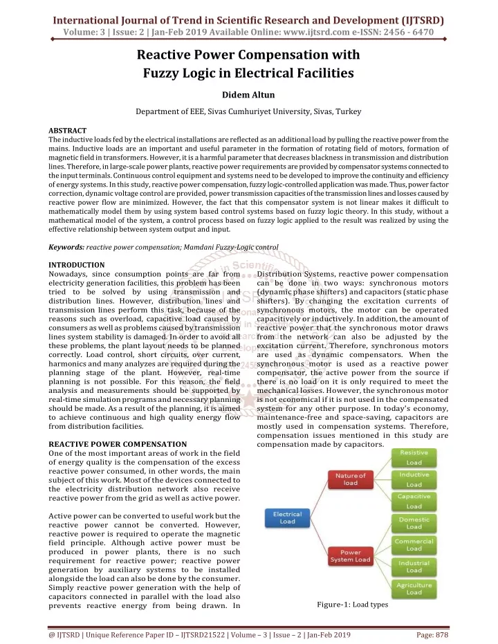
International Journal of Trend in Scientific Research and Development (IJTSRD) Volume: 3 | Issue: 2 | Jan-Feb 2019 Available Online: www.ijtsrd.com e-ISSN: 2456 - 6470 Reactive Power Compensation with Fuzzy Logic in Electrical Facilities Didem Altun Department of EEE, Sivas Cumhuriyet University, Sivas, Turkey ABSTRACT The inductive loads fed by the electrical installations are reflected as an additional load by pulling the reactive power from the mains. Inductive loads are an important and useful parameter in the formation of rotating field of motors, formation of magnetic field in transformers. However, it is a harmful parameter that decreases blackness in transmission and distribution lines. Therefore, in large-scale power plants, reactive power requirements are provided by compensator systems connected to the input terminals. Continuous control equipment and systems need to be developed to improve the continuity and efficiency of energy systems. In this study, reactive power compensation, fuzzy logic-controlled application was made. Thus, power factor correction, dynamic voltage control are provided, power transmission capacities of the transmission lines and losses caused by reactive power flow are minimized. However, the fact that this compensator system is not linear makes it difficult to mathematically model them by using system based control systems based on fuzzy logic theory. In this study, without a mathematical model of the system, a control process based on fuzzy logic applied to the result was realized by using the effective relationship between system output and input. Keywords: reactive power compensation; Mamdani Fuzzy-Logic control INTRODUCTION Nowadays, since consumption points are far from electricity generation facilities, this problem has been tried to be solved by using transmission and distribution lines. However, distribution lines and transmission lines perform this task, because of the reasons such as overload, capacitive load caused by consumers as well as problems caused by transmission lines system stability is damaged. In order to avoid all these problems, the plant layout needs to be planned correctly. Load control, short circuits, over current, harmonics and many analyzes are required during the planning stage of the plant. However, real-time planning is not possible. For this reason, the field analysis and measurements should be supported by real-time simulation programs and necessary planning should be made. As a result of the planning, it is aimed to achieve continuous and high quality energy flow from distribution facilities. REACTIVE POWER COMPENSATION One of the most important areas of work in the field of energy quality is the compensation of the excess reactive power consumed, in other words, the main subject of this work. Most of the devices connected to the electricity distribution network also receive reactive power from the grid as well as active power. Active power can be converted to useful work but the reactive power cannot be converted. However, reactive power is required to operate the magnetic field principle. Although active power must be produced in power plants, there is no such requirement for reactive power; reactive power generation by auxiliary systems to be installed alongside the load can also be done by the consumer. Simply reactive power generation with the help of capacitors connected in parallel with the load also prevents reactive energy from being drawn. In Distribution Systems, reactive power compensation can be done in two ways: synchronous motors (dynamic phase shifters) and capacitors (static phase shifters). By changing the excitation currents of synchronous motors, the motor can be operated capacitively or inductively. In addition, the amount of reactive power that the synchronous motor draws from the network can also be adjusted by the excitation current. Therefore, synchronous motors are used as dynamic compensators. When the synchronous motor is used as a reactive power compensator, the active power from the source if there is no load on it is only required to meet the mechanical losses. However, the synchronous motor is not economical if it is not used in the compensated system for any other purpose. In today's economy, maintenance-free and space-saving, capacitors are mostly used in compensation systems. Therefore, compensation issues mentioned in this study are compensation made by capacitors. Figure-1: Load types @ IJTSRD | Unique Reference Paper ID – IJTSRD21522 | Volume – 3 | Issue – 2 | Jan-Feb 2019 Page: 878
International Journal of Trend in Scientific Research and Development (IJTSRD) @ www.ijtsrd.com eISSN: 2456-6470 Reducing the reactive power of the electrical devices from the network by producing reactive energy at the desired location and in the desired amount is called reactive power compensation. Thus, it is approached to cosφ 1, which is called power factor. For example, if the power factor is 0.80 in the electricity distribution system, 80% of the apparent power is converted into useful power. This value is required to be as close to 1 as possible. This is because the reactive energy is limited and the electrical system elements are saved from overloading. production, facilities. ?The cost of production and sales of energy decreases. ?It is possible to keep the power of alternators and transformers smaller. ?Losses in distribution lines and reduced voltage drop ?If compensation is not made; ?Causes power losses on the network. ?Reduces the capacity of the production and distribution system. ?It has a voltage drop and causes a decrease in the energy carrying capacity in the distribution lines that limit the power carried. However, reaching a minimum number of solutions may not work well for many systems. Therefore, to increase the number of recommended levels and to extend the capacitor values to these stages. Because the capacitors that enable us to take big steps, it is necessary not to shrink them too much as they accelerate instant operations. At least if there are devices that attract a large load alone in the system, the capacitor values corresponding to the values of those devices should not be reduced. Basic equipment used in compensation systems; Current transformer, fuse, contactor or thyristor, capacitor, shunt reactor and reactive relay. FUZZY LOGIC SYSTEMS Fuzzy inference is that the output is mapped as a formulation with an input given using fuzzy logic. Sections that make up the fuzzy inference system are membership functions, logical operators and if-Then rules. Two types of fuzzy inference systems can be applied in the Matlab toolbox. These are fuzzy inference systems of mamdani and sugeno type [1-5]. These two types are different from each other in determining the output. Fuzzy inference systems have been applied successfully in areas such as automatic control, data classification, decision analysis, expert systems and computer vision. Due to its multidisciplinary nature, it takes fuzzy inference systems, fuzzy rule-based systems, fuzzy expert systems, fuzzy modeling, simple fuzzy systems, names associated with fuzzy controllers. Mamdani's fuzzy inference method presented in a study by Ebrahim Mamdani in 1975 is the basic methodology in this field. In this study, Mandani tried to control the combination of steam engine and steam boiler by synthesizing verbal control rules from experienced operators. Mandani's work is based on the publication of Lotfi Zadeh's fuzzy algorithms for complex systems and decision structures in 1973 [6]. Mandani type inference expects output membership functions to be fuzzy sets, as defined for the toolbox. After the collection process there is a fuzzy set that must be cleared for each output variable. Mandani uses the membership function, which is known as singleton membership function as the output transmission and distribution Electric Cable Reactive Load Active Load The actual load spent Without a reactive load, the cable cross-section could be chosen smaller or more active loads could pass through the cable. Figure-2: Electric cable load distribution Undesirable, useless load In this way, while the losses are reduced, the life of the system elements increases and their costs decrease. For this reason, each operation must control the reactive power it receives from the network, ie it must keep the power factor within certain limits. Reactive power compensation systems are used to achieve this. The reactive power control relay in these systems continuously measures the power factor of the plant and activates or deactivates the capacitor groups when necessary. Low Voltage Energy Input Load Reactive relay Capacitor Groups Counter Figure-3: Compensation block diagram in electrical facilities Reactive power compensation to be made in electrical facilities has advantages and disadvantages for the consumer and the manufacturer. Consumer advantages ?Conductors are selected in thinner section. ?Supply transformer, protection elements are selected in smaller values. ?The capacity and efficiency of the supply transformer and the plant increase. ?Less reactive energy is drawn from the grid. ?Energy consumption is reduced as the energy consumed decreases. control, control and ?Advantages in terms of manufacturer ?Conductors can be selected in a sub-section because the conductors will carry less current. ?As more active energy is transmitted from the same transmission line, the efficiency increases in @ IJTSRD | Unique Reference Paper ID – IJTSRD21522 | Volume – 3 | Issue – 2 | Jan-Feb 2019 Page: 879
International Journal of Trend in Scientific Research and Development (IJTSRD) @ www.ijtsrd.com eISSN: 2456-6470 membership function, and this can be considered as a pre-clarified fuzzy cluster [7]. FUNDAMENTALS OF MAMDANI TYPE FUZZY INFERENCE SYSTEM Mamdani type fuzzy model is very easy to create, very suitable for human behavior. It therefore has a very common use and is the basis of other fuzzy logic models. In this system, both input variables and output variables are expressed in the closed form membership functions [8-10]. A fuzzy inference system is created in the following five steps. ?Blur entries ?Implementation of Fuzzy Operators (AND OR) ?Extraction method implementation ?Collection of all outputs ?Clarifier Blurring Inputs: Using fuzzy expressions, it is the determination of membership degrees ranging between 0 and 1 using input variables. In Matlab fuzzy logic toolbox, input is always a numerical value. Application of fuzzy operators: If the given rule consists of more than one part, fuzzy operators are used to express the result with a single number for this rule. Fuzzy operator input is two or more membership values. The output is a single value. Toolbox supports two AND and two OR methods. AND: min (minimum) and prod (product). OR: max (maximum), and probabilistic OR method (probe). probe (a, b) = a + b - ab Applying the implication method: The rule weight must be determined before the extraction method is applied. Each rule has a weight ranging from 0 to 1. In general, the rule weight is 1. At this stage, the value obtained with the rule weight as a result of the 2nd stage is subjected to the AND process (the minimum is calculated). Collection of all exits: Since the decisions are based on a test of all rules in the fuzzy inference system, the rules must be combined in a way to make a decision. Each rule is combined into a single fuzzy set. The result of these processes is determined by using one of the three methods (Max, sum, probe) supported by Matlab. Stabilization: The input is a fuzzy set for the resurfacing process and the output is an odd number. The most popular rinse method is to calculate the center (center of gravity) of the area under the curve. APPLICATION In the example described here, a 220 Volt motor with inductor resistance Ra=0,20 Ω, field strength Rf=70 Ω R and n=1900 r/min. When the line current and load are increased, the load changes in the motor are corrected by changing the line current. At the same time the inductive current changes in the emf and motor speed. The values for the different welding voltages are given in Table 1. The purpose of fuzzy control is to keep the motor speed constant when the load changes. This speed control is made by adjusting the field current. The fuzzy controller has input speed for the motor speed and field current, while the field current is the output variable. Table-1: Calculated motor current, counter emf and speed values Ih (A) If (A) Ia (A) Ea (V) n (rpm/min) 82 2 80 72 2 70 62 2 60 52 2 50 42 2 40 32 2 30 22 2 20 10 2 8 2 2 0 Fuzzy logic rules for this problem are as follows. IF Speed ......... AND Field Current (at this speed) ....... if THEN Field Current (required speed control) .............. From the generated algorithm, the motor speeds for different loading levels, line voltages and field resistances were calculated. Similar calculations given in Table 1 are based on cluster results. Fuzzy logic relationships for machine data and rates, speed and field current are given in Table 2 and Table 3. Table-2: Fuzzy variable relation of velocity Fuzzy Relationship VLS Very low speed LS low speed NS Normal speed FF Fast VF Very fast Using Table 2 and Table 3, the fuzzy sets required for the field current and motor speed for the controller are given in Figure 2. The error signal indicating the difference between the actual speed and the reference (constant) speed is ignored as shown in the block diagram of Figure 3. As shown in Table 2 and Table 3, the fuzzy logic system is given by mapping the relationship between the input variables and the output variables of Fuzzy Associated Memory (FAM). The output variable is the current required to correct the motor speed in the normal range. By selecting a shorter interval value, the larger field current causes more copper and iron losses, and efficiency is reduced. Table-3: Fuzzy variable relation of field current Fuzzy Relationship SN Subnormal N Normal AN Above Normal L Long 199 202 204 207 210 212 215 217 220 1725 1770 1810 1855 1900 1942 1985 2025 2060 Description Range (rpm/min) 1600-1800 1785-1885 1885-1925 1915-2015 2000-2200 Description Range (rpm/min) 2.45-2.93 2.90-3.12 3.10-3.42 3.40 @ IJTSRD | Unique Reference Paper ID – IJTSRD21522 | Volume – 3 | Issue – 2 | Jan-Feb 2019 Page: 880
International Journal of Trend in Scientific Research and Development (IJTSRD) @ www.ijtsrd.com eISSN: 2456-6470 the motor speed to 1900 rpm at variable load conditions. If the current is 1.40 A and the speed is 1710 rpm, THEN bring the current to 2.10 A to normalize the speed. If the current is 1.40 A and the speed is 1845 rpm, THEN bring the current to 2.33 A to normalize the speed. CONCLUSION It has become a technical and economic necessity to improve the power factor by compensating the electrical facilities and to provide the best possible active and reactive energy for the buyers. In this study, fuzzy control algorithm is developed by determining the fuzzy variables and membership functions and fuzzy logic controller direct self-control method simulation results are obtained according to the determined rules. REFERENCES [1]T. Takagi and M. Sugeno, “Fuzzy identitication of systems and its application to modeling and control,” IEEE Trans. Syst., Man, Cybern., vol. 15, pp. 116132, 1985. Figure-4: Fuzzy sets of field current and engine speed Figure 3 illustrates a simulation model for DC motor speed control. The desired motor maintains its rated speed during load changes. Here, the speed error signal is found by comparing the actual motor speed with the reference speed. With the fuzzy logic controller, this error signal and the measured field current are brought to the reference speed and the appropriate field current is determined. This set a set of rules on the specified input and output variables, and the resulting membership functions are created. The relationship between the input and output variables is based on 24 rules, which are formed in Table 3. It should be noted that if the speed is too low (VLS) and the field current is short (S), there is no decrease in the field current when the speed is corrected. Table-4: Fuzzy Relationship Memory (FRM) table Speed VLS Field Current S SN N N AN AN N L SN In Table-4, the Table of Fuzzy Relationship Memory (BIH) is given. If the machine is in over speed mode (AN) and the field current is short (S) then the field current must be reset to normal (N) to reduce the machine speed. At this known point, the following two rules are expressed. If Field Current is small and Speed is over Then Field current is normal If the field current is large and the speed is lower Then the field current is below normal By changing the load, the controller speeds up the speed. The new output is compatible with the BIH table and shown below. The fuzzy logic control makes [2]E. H. Mamdani and S. Assilian, “Applications of fuzzy algorithms for control of simple dynamic plant,” Proc. Inst. Elec. Eng., vol. 121, pp. 1585-1588, 1974. [3]M. Sugeno and G. T. Kang, “Fuzzy modeling and control of multilayer incinerator,” Fuzzy Sets and Systems, vol. 18, pp. 329-346, 1986. [4]K. Tanaka and M. Sugeno, “Stability of analysis of fuzzy systems using Lyapunov’s direct method and construction procedure for Lyapunov functions,” in Proc. 6th Fuzzy Systems Symposium (Tokyo), 1990, pp. 353-356. LS NS FF VF AN SN AN N SN S AN AN AN AN AN N SN L [5]M. Sugeno and T. Takagi, “A new approach to design of fuzzy controller,” in Advcinces in Fuzzy Sets. Possibility Theory, and Applications, P. P. Wang and S. K. Chang, Eds. New York Plenum Press, 1983,pp. 325-334. SN N AN L N SN [6]L. A. Zadeh, “Fuzzy algorithm,” Information and Control, vol. 12, pp. 94-102, 1968. [7]D. Driankov, H. Hellendoorn, and M. Rainfrank, An Introduction to Fuzzy Control, Berlin: Springer-Verlag, 1993. [8]H.-X. Li and H. B. Gatland, “A new methodology for designing a fuzzy logic controller,” IEEE Trans. Syst., Man, Cybern., vol. 25, pp. 505–512, 1995. [9]J. Zhang, P. Shi and Y. Xia, "Fuzzy Delay Compensation Control for T-S Fuzzy Systems Over Network," in IEEE Transactions on Cybernetics, vol. 43, no. 1, pp. 259-268, Feb. 2013. [10]C. N. Bhende, S. Mishra and S. K. Jain, "TS-fuzzy- controlled active power filter for load compensation," in IEEE Transactions on Power Delivery, vol. 21, no. 3, pp. 1459-1465, July 2006. @ IJTSRD | Unique Reference Paper ID – IJTSRD21522 | Volume – 3 | Issue – 2 | Jan-Feb 2019 Page: 881