Download
1 / 7
70 likes | 76 Views
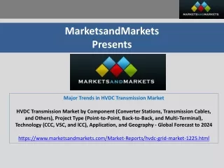
The continuously increasing demand for electric power and the economic access to remote renewable energy sources such as off shore wind power or solar thermal generation in deserts have revived the interest in high voltage direct current HVDC multiterminal systems networks . A lot of work was done in this area, especially in the 1980s, but only two three terminal systems were realized. Since then, HVDC technology has advanced considerably and, despite numerous technical challenges, the realization of large scale HVDC networks is now seriously discussed and considered. For the acceptance and reliability of these networks, the availability of HVDC circuit breakers CBs will be critical, making them one of the key enabling technologies. Numerous ideas for HVDC breaker schemes have been published and patented, but no acceptable solution has been found to interrupt HVDC short circuit currents. This paper aims to summarize the literature, especially that of the last two decades, on technology areas that are relevant to HVDC breakers. By comparing the mainly 20 years old, state of the art HVDC CBs to the new HVDC technology, existing discrepancies become evident. Areas where additional research and development are needed are identified and proposed. for the couple of well known applications are discussed. Mohd Liaqat "HVDC System: a Need for Future Power Transmission" Published in International Journal of Trend in Scientific Research and Development (ijtsrd), ISSN: 2456-6470, Volume-3 | Issue-2 , February 2019, URL: https://www.ijtsrd.com/papers/ijtsrd20318.pdf Paper URL: https://www.ijtsrd.com/engineering/electrical-engineering/20318/hvdc-system-a-need-for-future-power-transmission/mohd-liaqat<br>

E N D
International Journal of Trend in Scientific Research and Development (IJTSRD) Volume: 3 | Issue: 2 | Jan-Feb 2019 Available Online: www.ijtsrd.com e-ISSN: 2456 - 6470 HVDC System: a Need for Future Power Transmission Mohd Liaqat M.Tech Scholar, Electrical Engineering Department, Yamuna Institute of Engineering & Technology, Yamunanagar, Haryana, India ABSTRACT The continuously increasing demand for electric power and the economic access to remote renewable energy sources such as off-shore wind power or solar thermal generation in deserts have revived the interest in high-voltage direct current (HVDC) multiterminal systems (networks). A lot of work was done in this area, especially in the 1980s, but only two three-terminal systems were realized. Since then, HVDC technology has advanced considerably and, despite numerous technical challenges, the realization of large-scale HVDC networks is now seriously discussed and considered. For the acceptance and reliability of these networks, the availability of HVDC circuit breakers (CBs) will be critical, making them one of the key enabling technologies. Numerous ideas for HVDC breaker schemes have been published and patented, but no acceptable solution has been found to interrupt HVDC short-circuit currents. This paper aims to summarize the literature, especially that of the last two decades, on technology areas that are relevant to HVDC breakers. By comparing the mainly 20+ years old, state-of-the art HVDC CBs to the new HVDC technology, existing discrepancies become evident. Areas where additional research and development are needed are identified and proposed. for the couple of well-known applications are discussed. KEYWORDS: Distributed generation; Renewable energy sources; Fuel cell systems; Power-conditioning units; dc/dc converters; dc/ac inverters I. INTRODUCTION In recent years, the interest in HVDC multiterminal systems has been revived. The continuously increasing demand for electric power and the economic access to remote renewable energy sources such as off-shore wind power [1]–[2][3] or solar thermal generation in deserts [4] require an electric energy transmission system that bridges very long distances with low losses. Traditional HVDC point-to-point systems can help to serve this duty and are available today. Linking more than two HVDC terminals to form a meshed multiterminal HVDC system (network) would have several advantages: the reduction in the number of terminals (reduced costs and losses), the outage of one dc line does not interrupt the power flow at any terminal, each terminal can operate at different power and current, and the power exchange with all ac connection points can be fully controlled. It is thus very attractive to explore the realization of HVDC networks. There was considerable interest in multiterminal HVDC systems in the 1980s, but only two three-terminal systems were realized [5], [6]. The advances in HVDC technology also helped to renew the interest in HVDC networks. In particular, the voltage-source converter (VSC) HVDC is now available. However, the acceptance of HVDC networks with respect to efficiency, reliability, and controllability will strongly depend on the availability of HVDC circuit breakers (CBs), making them one of the key enabling technologies [7]–[8][9][10]. There are significant differences between the requirements of ac and dc CBs, mainly due to the absence of a natural current zero crossing in dc systems. DC breakers have to interrupt short-circuit currents very quickly and need to dissipate the large amount of energy which is stored in the inductances in the system. Today, dc CBs are only widely available for the low- and medium-voltage range. For HVDC applications, only transfer and load current switches are in use. Breakers interrupting HVDC short-circuit currents are not commonly available and have very limited ratings. Numerous proposals for breaker designs have been presented in articles and patent applications. All comprise different series and parallel connections of classical ac interrupters, resonance circuits with inductors and capacitors, semiconductors, charging units, varistors, or resistors. Each of the numerous concepts has certain advantages and drawbacks. Most of the publications address only a few, or even only a single aspect of the many requirements, but no contribution has tried to give an overall picture. The main aim of this paper is to give an overview of HVDC CBs, to identify areas where research and development are needed, and, by this, to revive the discussion on this subject. Obviously, this paper cannot discuss each of these identified needs in detail. But by citing relevant literature, it should serve as a reference point for others working in this area. II. HVDCNETWORKS HVDC systems have two main uses: 1) to connect two ac networks with different frequencies or different frequency- control philosophies (back-to-back) or 2) to transmit large amounts of power via long distances. For large distances, dc transmission lines have lower losses than ac connections. “Long” in this context means more than ∼800 km for overhead lines, and more than ∼40 km for cables. There are two basic converter technologies in use today for HVDC power transmission: the “classical” CSC technology based on thyristors and the more recent self-commutated VSC technology based on insulated-gate bipolar transistors (IGBTs) [11]–[12][13][14][15]. Since thyristors are only turn-on devices, the active power flow of CSC systems is controlled by adjusting the turn-on (firing) and the extinction time instant (overlap) prior to commutation to another valve. Reactive power is consumed by the rectifier at the sending, and by the inverter at the receiving end. This has to be compensated for by filters and additional capacitors on the ac sides. In particular, under transient conditions, the amount of reactive power @ IJTSRD | Unique Reference Paper ID - IJTSRD20318 | Volume – 3 | Issue – 2 | Jan-Feb 2019 Page: 165
International Journal of Trend in Scientific Research and Development (IJTSRD) @ www.ijtsrd.com eISSN: 2456-6470 consumed varies greatly. The power flow is unidirectional. The reversal of the power-flow direction requires a change in polarity of the system, which could be problematic, in particular, for polymeric cable connections. The technology is quite mature and two 800-kV systems have been put in operation recently with power levels of up to 6400 MW (800 kV, 4 kA, bipolar) [16]. The losses in one terminal are ∼0.7% [17] at rated current, of which the converter transformer contributes ∼50%. The technology is still advancing and further developments which occurred recently are within the thyristor switch itself where voltage and current ratings are continuously increasing, in the application of capacitor-commutated conversion which consumes considerably less reactive power [18], [19], or in the reduction of filter size by using continuously tuned ac filters and active dc filters [12], [18]. With the advances in power semiconductor devices and the availability of high-power transistors (IGBTs [20], [21]), it is also possible to use pulse-width modulation (PWM) or multilevel concepts for HVDC power transmission. The self- commutated VSC has a stiff dc voltage, and large capacitors are used. Due to the use of PWM, only high-frequency harmonics are present and the filters can be considerably smaller. VSC HVDC technology transmits active power and can provide the required amount of reactive power at both the power sending and the power receiving end. This also allows a reduction of the filter size. However, the losses in one VSC terminal are ∼1.6% [17], [22], of which the converter valves contribute almost 70%. The largest realized VSC-based HVDC system is 150 kV, 400 MW [23] and a 300- kV, 800-MW system is in the planning phase (BorWin2). The technology is, in principle, available for higher powers today, limited mainly by the voltage constraints of XLPE dc cables. In case of a dc-side fault, the diodes connected in parallel to the IGBT modules act as an uncontrolled rectifier, even if the IGBTs are blocked. The short-circuit current is limited only by the ac system [14]. The small dc-side inductance leads to a very high rate of rise of dc current. In addition, the dc capacitors discharge and add to the fault current [24], [25]. Thus, the dc and ac sides have to be decoupled very quickly to stop the fault current. Since the converter is no longer controllable in this fault case (in contrast to CSC HVDC systems), ac CBs are typically used. HVDC CBs could do the same, but are not available today. Due to this vulnerability to dc-side faults, VSC HVDC stations are preferably connected by cables rather than overhead lines since cables are much less sensitive to environmental influences. The key differences between CSC- and VSC-based HVDCs are summarized in Table I. With respect to HVDC CBs, the most important ones are the different sizes of capacitances and inductances (and the resulting different rate of rise of the fault current) and the loss of control in the VSC HVDC in case of a dc-side fault. VSC technology is advancing rapidly. New concepts have been proposed and partly demonstrated on a small scale. The aim is to reduce losses to <1%, to reduce the harmonics content, and even to have the ability to limit and extinguish the current in case of dc-side faults [26]–[27][28]. Fig.1. Sample comparison of the HVDC network configuration based on point-to-point systems (left) or with the use of HVDC CBs (right). Most of today's HVDC transmission systems are point to point, connecting only two terminals. In principle, it is possible to connect a number of ac nodes with many point- to-point connections in configuration (cf. left-hand side of Fig. 1). However, there are several advantages if the lines were connected on the dc side, forming a true HVDC network (e.g., like on the right- hand side of Fig. 1). First, the number of converter stations could be reduced since only one converter is needed per ac connection point. Not only does this significantly reduce the costs, but also the losses of the entire transmission system. In addition, each station can transmit (send or receive) power individually and can even change from receiving to sending power without requiring that another station do the opposite. There is more redundancy, and power can be transmitted even if one line is lost. In order to ensure the reliable operation of a multiterminal system, it must be possible to decouple faulty lines or stations from the system. In ac systems, CBs that are able to interrupt the full short- circuit current are used. For HVDC, realized CBs have only limited ratings. Compared with ac CBs, they are much larger in size and considerably more expensive. Thus, other concepts have been introduced in today's point-to-point systems. Most commonly, dc line faults are interrupted using converter control [29], which only works for CSC, or the CBs on the ac side of the converter stations are operated to de- energize the station and the line [30]. In case of a nonsustained fault, the stations and the line can be re- energized. This operation sequence takes at least a few 100 ms [23], [31], [32] up to a few seconds [33], but is well suited for point-to-point connections. De-energizing the entire HVDC networks has also been suggested [24], [34], [35], but it is surely limited to small systems with only three or four terminals [36]. The availability of HVDC CBs is thus a key enabling technology for the reliable and economic operation of multiterminal HVDC systems. Supporting HVDC CBs with fast action of the terminal controls is undoubtedly advantageous and should be investigated further (in particular, also for VSC topologies). III. HVDC CIRCUIT BREAKERS In today's point-to-point HVDC transmission systems, dc interrupters are used for several different switching duties. A neutral bus switch (NBS), neutral bus ground switch (NBGS), metal return transfer breaker (MRTB), ground return transfer breaker (GRTB), high-speed bypass switch (HSBS) for parallel line switching, and isolation switches also exist. Interrupters to break dc short-circuit currents have only been realized in very limited numbers and maximum ratings are 250 kV, 8 kA or 500 kV, 4 kA, which is not more a so-called multiple-pair @ IJTSRD | Unique Reference Paper ID - IJTSRD20318 | Volume – 3 | Issue – 2 | Jan-Feb 2019 Page: 166
International Journal of Trend in Scientific Research and Development (IJTSRD) @ www.ijtsrd.com eISSN: 2456-6470 than 1.6 times the rated nominal current. The breaking time is in the order of 35 ms, but as stated before, for CSC-based systems, the large inductances limit the rate of rise of fault current, and this time is sufficiently fast. However, the components of these breakers are very large and more costly than ac CBs with comparable current and voltage ratings. In point-to-point HVDC transmission systems, the function of dc breakers has thus typically been substituted by de- energizing the converter stations (e.g., by acting with the station control or by operating the breakers on the ac side and the opening of isolation switches). In low- and medium- voltage dc applications, short-circuit current interrupting breakers have been realized based on several different technologies (e.g., switching arcs or solid-state switches). The difficulties in realizing HVDC CBs can be attributed to the demanding requirements on CBs in dc systems which are quite different than those of ac CBs. One of the major differences is the absence of natural current zero crossings in dc systems. The breakers have to fulfill the basic requirements (cf. also [54]) as follows. 1.Create a current zero crossing to interrupt the current. 2.Dissipate the energy stored in the system inductance. 3.Withstand the voltage response of the network after current interruption. In particular, the first two requirements lead to a very strong interaction between the breaker and the dc system, an attribute which is also very different than AC CBs. In addition to these basic requirements, there are, depending on the breaker application, additional secondary requirements as follows. ?In VSC-based systems, the HVDC breaker has to be able to interrupt quickly, as was stated before. ?The maximum voltage generated by the breaker must be low enough to comply with the insulation coordination of the dc system. This is particularly important for switching of load currents where the network is at nominal voltage. As mentioned before, the interest in meshed HVDC systems is almost as old as the HVDC technology itself. In parallel to the interest in HVDC networks, a great amount of research and development was done on HVDC breakers up to the 1980s and was summarized in 1971, 1983, and partly in 1991. Thus, only the basic dc breaker concept is explained here. The details of different variants of this concept can be found in the earlier reviews. After 1985, the interest in HVDC breakers dropped significantly and only in recent years, when the interest in HVDC networks has picked up again, new studies appear. Advances have mainly been made in related technologies that could help to improve the HVDC CB design. The focus in this paper will be on reviewing the more recent developments, in particular, keeping in mind also the new VSC technology. A.Basic Working Principles of HVDC CBs The current in a dc circuit can be brought to zero by generating a counter voltage of similar or larger amplitude than the system voltage. This counter voltage can be produced by inserting additional resistance or inductance in the current path. The energy of the dc system is dissipated across this device. The larger the counter voltage, the smaller the time needed to interrupt, but the larger the energy that is dissipated in the device. DC breakers with current limiting and energy dissipating function of an arc are commonly used in LV and MV applications. Some proposals for high-voltage systems have been made, but none of them has proven efficient and successful in real applications. An alternative is to have several parallel paths in the breaker and to separate the requirements to different elements. The simplest is one nominal current path and one parallel path with a linear or nonlinear resistive element. The nominal current path typically consists of an interrupter with low ohmic losses in closed position, which is, so far, only possible with movable metallic contacts. Upon opening of these contacts, an arc is established and its arcing voltage is used to commutate the current to the resistive path where the energy of the system is then dissipated. The advantage is that the interrupter in the nominal current path only needs to produce a voltage sufficient for commutation and not for counteracting on the full system voltage. In addition, the breaker does not have to have a large energy dissipating function, which typically improves its interruption capability. If the commutation path only consists of a linear resistor, the arc voltage of the interrupter still has to be very high. A gradual insertion of resistors or nonlinear resistors to limit the required commutation voltage would be better. The commutation process can be eased by adding other elements, such as a capacitor which temporarily takes the current flow. More recent developments make use of actively controllable resistances of solid-state devices (cf. Section III- B). Fig. 2. Basic arrangement of the HVDC CB For most of the practically realized HVDC CBs, separate commutation and energy absorbing paths have been used, as sketched in Fig. 2. The commutation path may then be a series resonance consisting of a capacitance Cc and inductance Lc so that current oscillation between the nominal and the commutation path can occur at the natural frequency ω20=1/LcCc. If the amplitude of the oscillating current in is larger than the system dc current I0, a current zero crossing occurs in the nominal path, and the interrupter Sn can interrupt the current. Current I0 continues to flow, charging the capacitor Cc in the commutation path. If the capacitor voltage exceeds a given value, typically chosen to be the voltage capability of the breaker or the insulation coordination of the HVDC system, the energy absorption path acts, causing the system current I0 to decrease. If the differential arc resistance dU/dI of the interrupter in the nominal path is negative, a current oscillation between the nominal and the commutation path with increasing amplitude occurs, started by the natural fluctuation in the arc voltage. Fig. 3 shows the currents in the different paths of the breaker and the voltage across it. At time t0, a fault occurs and the current I0 starts to increase. The interrupter contacts of @ IJTSRD | Unique Reference Paper ID - IJTSRD20318 | Volume – 3 | Issue – 2 | Jan-Feb 2019 Page: 167
International Journal of Trend in Scientific Research and Development (IJTSRD) @ www.ijtsrd.com eISSN: 2456-6470 the nominal current path separate at t1, and an instable oscillation starts due to the characteristics of the arc voltage. At t2, the amplitude of the oscillation is sufficiently large so that in crosses zero and Sn interrupts. The current quickly charges Cc until the threshold voltage level of the energy absorbing elements in the third path is reached at time t3. This path can consist of energy absorbing linear or nonlinear resistors that are inserted with switch Se or be nonlinear ZnO varistors that become partly conductive only above a certain applied voltage and, thus, do not need an insertion device. The voltage is limited by these elements, current only flows through the energy absorbing path, and the current I0 of the system ceases. In alternative to the self-excited growing oscillations with purely passive components in the commutation path is the use of additional active components, such as the closing switch Sc. If the capacitor Cc is precharged, a current is injected into the nominal path upon closing of Sc and a counter-current is induced active current injection with the precharged capacitor is chosen, a large Cc/Lc ratio is advantageous since it leads to larger injected current with the same energy stored in the capacitor. Also here, a set of criteria combining the Cc/Lc- ratio with the natural frequency ω0 is chosen to maximize the interruption performance. The current oscillations in the nominal and commutation path of passive arrangements grow if the arc characteristic is negative. A fast-growing oscillation at a high natural frequency leads to faster current interruption. The ac CBs that are typically used as elements in the nominal path are by no means optimized for this. Thus, dedicated investigations studying the arc characteristics under different conditions have been performed and optimizing the breaker was tried. Nonetheless, as the classical configuration with only passive elements is probably the most economic and reliable one, further investigation of the arc behavior under different conditions to optimize the breaker is surely needed. A dedicated arcing chamber for optimal excitation of the oscillations could become interesting if an HVDC network becomes reality and the number of breakers that is needed grows. This chamber does not necessarily have to have high interruption capability since another breaker, dedicated for current interruption, could be placed in series in the nominal current path. In addition to the passive variant, the growing oscillations can also be actively excited. In [24], adding a power transistor in parallel to the interrupter in the nominal current path that is pulsed at the natural frequency ω0 between conducting and an appropriate high voltage level is proposed. This pulsing excites the current oscillation, preferably faster and more reliably than the instable arc condition can. The development and optimization of these breakers requires sophisticated testing (cf. also later section) and there have been attempts to substitute some of the tests with simulations. The interaction of the breaker with a real network is modeled with programs [25], [26], where the arc is represented by a black- box model [27]with some free parameters that are fitted to experiments. So far, the focus of these simulations was more on the behavior of the network rather than optimizing the breaker itself. As long as the programs are run with black-box models, these models have to be verified and calibrated by basic arc measurements. An optimization of the breaker with these type of simulations must always be accompanied by experiments. Progress has been made in simulating ac switching arcs of gas CBs and vacuum interrupters using multiphysics simulations that need less, or even no fitting parameters at all. These type of simulations should be used to optimize the arcing conditions for use in HVDC CBs in addition to black-box models. Equally important as the oscillation excitation is the interruption capability of the interrupter. In contrast to ac CBs, the current slope dI/dtbefore current zero and the rate of rise of the transient recovery voltage dU/dt (RRTRV) across Sn after current interruption are determined by the breaker itself and not by the network. The current slope before interruption depends on the oscillation frequency and amplitude (growth) and may vary over a large range. The switching arc gap is stressed by the voltage of the capacitor, charged by I0, in the parallel path. A detailed understanding of the current interruption process and the interruption limits of the breaker with different arcing conditions is necessary and has to be gained by experiments and simulations. Vacuum CBs have been proposed as building elements for HVDC CBs since they combine a high transient simulation Fig. 3. Basic current and voltage development during interruption IV. MORE RECENT ACTIVITIES AND RELATED FIELDS OF TECHNOLOGY 1.Adaptions of the Basic Principle The basic principle of HVDC CBs, as shown in Fig. 2, and described in the previous section, has been continuously optimized. Special focus is on making better use of the most costly components, the capacitors, and varistors. Methods have been derived to calculate and select the optimum value of the capacitor Cc and to extend the current interruption range. In a configuration with a passive commutation path, a set of criteria is derived based on the characteristic surge impedance Lc/Cc and the characteristic frequency ω0.The criteria are chosen to minimize the interruption time and to enhance the interruption performance. If the configuration of interruption performance @ IJTSRD | Unique Reference Paper ID - IJTSRD20318 | Volume – 3 | Issue – 2 | Jan-Feb 2019 Page: 168
International Journal of Trend in Scientific Research and Development (IJTSRD) @ www.ijtsrd.com eISSN: 2456-6470 (large dI/dt with large dU/dt) with small breaking times (<5ms). Unfortunately, the maximum voltage withstand of vacuum interrupters is limited to MV levels (Un≤36 kV) and only a series arrangements could reach high-voltage levels. This is mechanically very demanding and needs to be studied in further detail. Depending on the selected HVDC technology, the focus of future research in optimizing the existing schemes is placed on one of the directions mentioned before. The requirement of fast interruption will be especially challenging to meet with a classical configuration. Another application of a similar configuration is for the magnetic coils of the planned fusion experiment ITER, which are planned to operate with 70-kA dc current. This leads to a stored magnetic energy of 40 GJ. If a fault in the superconducting coils is detected, this current needs to be interrupted and the energy dissipated within ∼11 s. The interrupter scheme is composed of a bypass switch in parallel with an interrupter and a counter current injection from a precharged capacitor. The current is commutated to a discharge resistor where the energy is dissipated. The nominal current and energy rating are considerably higher than for HVDC CBs, but the rated voltage is only 17.5 kV and the interruption time is 500 ms. 2.Combined Optimization of Topology, Control, and Breaker Most of the research on HVDC, multiterminal schemes, and HVDC CBs focuses only on a particular individual aspect. Sometimes the breaker is assumed to be known, and the network control is designed around it. Other times, the requirements for HVDC CBs are set by the system control activities and the breaker has to be designed accordingly. No combined attempts to optimize the system as a whole are reported. It would be thinkable to adjust the control scheme to ease the requirements for CBs. Adding additional inductance to the dc side in VSC-based networks would limit the rate of rise of the short-circuit current and simplify the hard breaking time requirement, but would lead to slower control in normal operation. If high impedance grounding is used, the short-circuit current during dc-line-to-ground faults is limited. Focusing on only one aspect is most probably not optimum as only a combined optimization could lead to the globally best solution. Another example for combined optimization is for VSC schemes using multilevel converters. Voltage levels at a fraction of the total dc line voltage occur inside the valve and, in principle, it would be possible to interrupt at these levels. The respective dc breakers would have a lower voltage rating, but the topology of the valves needs to be redesigned to incorporate dc breakers. Only a combined effort of valve and breaker design would lead to a satisfying result. 3.Standardization A new multiterminal HVDC system will be built using components from more than one manufacturer. Standards and norms for the multiterminal HVDC should be set. This is particularly important for CBs and their interfaces to the network and protection system. 4.Solid-State DC Breakers Also discussed are pure semiconductor switches, not only for HVDC, but also for low- and medium-voltage dc and ac. The clear advantage is that the switching time can be as low as a few microseconds, compared to a few (ten) microseconds of a mechanical switch with separating metal contacts. The main drawbacks are costs and the fact that the resistance in conducting mode is in the order of a few mΩ and, thus, considerably higher compared to a few μΩ for a mechanical switch. The full forward conduction losses of the solid-state devices are ∼0.10.1–0.4% of the transmitted power. The application of semiconductor switches was thus typically limited to applications where high PQ is of crucial importance and the minimum breaking time is absolutely needed. As stated before, the rate of rise of short-circuit current in VSC- based HVDC networks is very high. So far, no other HVDC CB concept is available with breaking times in the order of 1 ms and, thus, a solid-state switch is the only feasible solution today. A single semiconductor device is not able to withstand the full voltage and current rating, but a series and parallel arrangement of several switches is possible to achieve HVDC CB ratings. Research and development in the solid-state switching devices, the semiconductor material itself, and in concepts where the high on-state losses of solid-state switches can be avoided, so-called hybrid concepts have to be intensified. This is discussed in the following two sections. 5.Semiconductor Devices The performance of semiconductor devices continues to increase constantly, not only in blocking voltage rating, but also in maximum current rating for a single chip. In the future, HVDC valves and potentially also HVDC CBs can be realized with fewer components, which improves the performance and decreases the losses. Today, all devices are based on silicon and an even bigger step ahead would be the change of semiconductor material to a wide bandgap material. SiC, GaN, and diamond have been discussed and are intensively investigated. Wide bandgap materials have higher breakdown field strengths Ec compared to Si (Si: 0.3, SiC: 1.2– 2.4, GaN: 3.3, and diamond: 5.6 MV/cm). For comparable voltage capability, the chip could be significantly thinner which decreases the losses of the device. For example, a SiC- pin-diode was fabricated with 4.2-kV breakdown voltage with 5 times lower conduction losses than Si-based diodes with comparable ratings. Still, no competitive wide bandgap devices are commercially available, but research and development is pursued intensively in this region and great advances can be expected in the following years or decades. Any progress in this area will influence HVDC technology significantly, including the possibility of designing solid-state HVDC CBs. 6.Hybrid CBs It was already stated in the previous section that semiconductors have high conduction losses and are thus not optimal as inline switches or CBs. Hybrid switching schemes are therefore proposed. Here, the nominal current path contains a mechanical breaker with low-resistive metal contacts that are separated quickly, causing the current to commutate to a parallel path with the semiconductor switch. When the current is transferred and the dielectric strength between the metallic contacts has recovered, the semiconductor switch is operated. Schemes are proposed for ac CBs; ac capacitor switches; fault-current limiting units; and for dc CBs. Other hybrid concepts, where gas and vacuum CBs are connected in series, exist as well. Here, speed is not the primary aim, but the combination of the high-current and @ IJTSRD | Unique Reference Paper ID - IJTSRD20318 | Volume – 3 | Issue – 2 | Jan-Feb 2019 Page: 169
International Journal of Trend in Scientific Research and Development (IJTSRD) @ www.ijtsrd.com eISSN: 2456-6470 high-frequency interruption capability of vacuum CBs, together with the high-voltage withstand capability of gas CBs. These schemes are continuously under discussion for both HVDC breakers and ac CBs. These types of hybrid concepts are of principal interest, but the interaction of different devices is often complex and makes a detailed understanding of the working principle and careful consideration, when coupling, necessary. 7.Fast Switches One of the key devices for hybrid dc CBs using solid-state switches is a very fast mechanical switch with low conduction losses in the nominal current path. These fast switches have to operate in <1 ms and to build up sufficient arc voltage to cause the current to commutate to the interruption path. Concepts for fast switches based on electromagnetically driven contacts in air or vacuum CBs have been developed. In low-voltage networks, these switches also have a current limiting function and ratings for CBs have reached 4 kA/1.5 kV with breaking time ∼300 μs. The requirements for fast switches in hybrid breakers operating in <1 ms are independent of ac or dc. For high-voltage systems, new concepts or series arrangements of many switches would be necessary and research should be carried out in this area. 8.Fault Current Limiters Many of the concepts to fulfill the basic requirements of an HVDC CB, as discussed before, are also applicable for fault current limiters (FCL) in ac and dc systems. The task of fault current limiters is, as the name implies, to limit the maximum overcurrent in a power system when a fault occurs. The FCL thus needs to increase the impedance of the systems, either self-triggered or externally triggered. The FCL has to be effective before the peak current is reached, typically 1–3 ms in 50-Hz ac systems. In addition, the FCL has to handle the large amounts of energy dissipated during the limitation. In addition, some FCLs also interrupt the current. If they cannot do so, a load break switch has to be placed in series to interrupt the limited current. Some review articles have been published and the details of FCL will not be repeated here. Amongst the different operation principles are solid-state fault current limiters (SSFCLs) and hybrid concepts using fast mechanical switches. Both concepts have been discussed before, but have not been realized for high voltages so far. Medium-voltage fuses work as self-triggered FCL with interruption capability, but they are one-shot devices which have to be replaced manually and are widely available only up to 10–20 kV. Superconducting fault current limiters (SCFCLs) of resistive type make use of the intrinsic physical property that superconductors lose their zero resistance above a critical current density. These types of fault current limiters have low conduction losses in nominal operation, are fast and resettable, but require extensive cooling of the material to reach the superconducting state. Resistive SCFCLs could be used as fast-acting commutation switches placed in the nominal current path, but disconnectors have to be placed in series since the SCFCL has no voltage withstand capability. Most fault current limiters have been designed for distribution voltage levels (<36 kV). For the higher voltages on the subtransmission and transmission level, only limiting reactors and resonance links with inline capacitors have been realized. Research and development for high-voltage FCL is ongoing and any progress in this area is also of benefit for HVDC CB activities. Even unconventional concepts as a series connection of SCFCL with puffer breaker in LN2 are investigated. V. CONCLUSIONS Throughout the previous sections of the text, several technological areas where research and development is needed in order to improve or enable HVDC CBs were identified and discussed. These areas are summarized in the list below as follows. Optimization of the existing basic HVDC CB scheme by optimizing the size of elements, such as capacitors, inductors, varistors, or charging units. The main goal is a reduction in size, interruption time, and costs. Optimization of switching arcs with respect to the growth of oscillation and capability to interrupt by detailed investigation of arc characteristics under many different conditions for gas and vacuum CBs. Derivation and verification of the parameters are in mathematical arc models. Multiphysics simulation of HVDC arcs are for high current (growing current oscillation) and interruption phase. Extension of medium-voltage CBs to higher voltage levels by either improving the technology, series connection, or by applying breakers across medium-voltage levels in multilevel converter topologies. Fast mechanical switches or disconnectors with high recovery voltage withstand and low on-state-losses. Ideally, these switches have sufficient arcing voltage for fast commutation. Use of such a switch in a hybrid CB. Pure semiconductor switch with minimal on-state losses. Use of new wide bandgap power semiconductor devices (e.g., SiC or GaN). Fault current limiters for medium and high voltage. Combined optimization of the whole system: breaker-control protection. New testing methods for HVDC CBs or its individual components. Due to the strong breaker-network interaction, power-hardware-in-the-loop advantageous. Standards and norms for multiterminal HVDC. REFERENCES [1]N. Kirby, L. Xu, M. Luckett, and W. Siepmann, “HVDC transmission for large offshore wind farms,” Power Eng. J., vol. 16, pp. 135–141, Jun. 2002. [2]W. Lu and B. Ooi, “Optimal acquisition and aggregation of offshore wind power by multiterminal voltage- source HVDC,” IEEE Trans. Power Del., vol. 18, no. 1, pp. 201–206, Jan. 2003. [3]C. Meyer, M. Hoeing, A. Peterson, and R. W. DeDoncker, “Control and design of DC grids for offshore wind farms,” IEEE Trans. Ind. Appl., vol. 43, no. 6, pp. 1475– 1482, Nov./Dec. 2007. [4]DLR, German Aerospace Center, Institute of Technical Thermodynamics, Section Systems Analysis and techniques would be @ IJTSRD | Unique Reference Paper ID - IJTSRD20318 | Volume – 3 | Issue – 2 | Jan-Feb 2019 Page: 170
International Journal of Trend in Scientific Research and Development (IJTSRD) @ www.ijtsrd.com eISSN: 2456-6470 Technology interconnection for concentrating solar power,” Tech. Rep., 2006. [Online]. http://www.dlr.de/tt/trans-csp, available: [5]Billon, J. Taisne, V. Arcidiacono, and F. Mazzoldi, “The Corsican tapping: From design to commissioning tests of the third terminal of the Sardinia-Corsica-Italy HVDC,” IEEE Trans. Power Del., vol. 4, no. 1, pp. 794– 799, Jan. 1989. [6]D. McCallum, G. Moreau, J. Primeau, M. Bahrman, B. Ekehov, and D. Soulier, “Multiterminal integration of the Nicolet converter station into the Quebec-New England Phase II HVDC transmission system,” in Proc. CIGRE 35th Int. Conf. on Large High Voltage Electric Systems, Paris, France, Aug./Sep. 1994, vol. 1, pp. 14- 103/1–14-103/9. [7]A. Greenwood, K. Kanngiessner, V. Lesclae, T. Margaard, and W. Schultz, “Circuit breakers for meshed multiterminal HVDC systems Part I: Introduction DC side substation switching under normal and fault conditions,” Electra, no. 163, pp. 98–122, Dec. 1995. [8]A. Greenwood, K. Kanngiessner, V. Lesclae, T. Margaard, and W. Schultz, “Circuit breakers for meshed multiterminal HVDC systems. Part II: Switching of transmission lines in meshed MTDC systems,” Electra, no. 164, pp. 62–82, Feb. 1996. [9]L. Bergstrom, L.-E. Juhlin, G. Liss, and S. Svensson, “Simulator study of multiterminal HVDC system performance,” IEEE Trans. Power App. Syst., vol. PAS- 97, no. 6, pp. 2057–2066, Nov. 1978. [10]K. Kanngiesser, H. Ring, and T. Wess, “Simulator study on line fault clearing by DC circuit breakers in a meshed MTDC system,” in Proc. Int. Conf. AC and DC Power Transmission, London, U.K., Sep. 1991, pp. 102– 107. [11]O. Krishan and Sathans, “Design and Techno-Economic Analysis of a HRES in a Rural Village,” Procedia Comput. Sci., 6th International Conference on Smart Computing and Communications, ICSCC 2017, 7-8 December 2017, Kurukshetra, India vol. 125, pp. 321–328, 2018. [12] J. Arrillaga, High Voltage Direct Current Transmission, 2nd ed. Exeter, U.K.: Short Run Press, 1998, Inst. Elect. Eng. [13]J. Arrillaga, Y. H. Liu, and N. R. Watson, Flexible Power Transmission: The HVDC Option. Hoboken, NJ: Wiley, 2007. [14]M. Bahrman and B. Johnson, “The ABCs of HVDC transmission technologies,” IEEE Power Energy Mag., vol. 5, no. 2, pp. 32–44, Mar../ Apr. 2007. [15]N. Flourentzou, V. Agelidis, and G. Demetriades, “VSC- based HVDC power transmission systems: An overview,” IEEE Trans. Power Electron., vol. 24, no. 3, pp. 592–602, Mar. 2009. [16]B. Andersen, L. Xu, P. Horton, and P. Cartwright, “Topologies for VSC transmission,” Power Eng. J., vol. 16, p. 142, Jun. 2002. [17]Q. Yuan and L. Yun, “Xiangjiaba-Shanghai highest power of UHVDC ready for implementation,” in Proc. IEEE Power Eng. Soc. Transmission and Distribution Conf. Expo., Apr. 2008, pp. 1–5. [18]O. Krishan and Sathans, “Frequency regulation in a standalone wind-diesel hybrid power system using Assessment, “Trans-Mediterranean pitch-angle controller,” in Proceedings of the 10th INDIACom; 2016 3rd International Conference on Computing for Sustainable Global Development, INDIA Com 2016, 2016. [19]O. Krishan and Sathans, “Optimum sizing and economical assessment of grid integrated hybrid system for a rural village: A case study,” in 1st IEEE International Conference on Power Electronics, Intelligent Control and Energy Systems, ICPEICES 2016, 2017. [20] H. Pang, G. Tang, and Z. He, “Evaluation of losses in VSC-HVDC transmission system,” in Proc. IEEE Power and Energy Soc. Gen. Meeting—Conversion and Delivery of Electrical Energy in the 21st Century, Pittsburgh, PA, Jul. 2008, pp. 1–6. [21]L. Carlsson, ““Classical” HVDC: Still continuing to evolve,” Modern Power Syst., vol. 22, pp. 19–21, Jun. 2002. [22]A. Gole and M. Meisingset, “Capacitor commutated converters for long-cable HVDC transmission,” Power Eng. J., vol. 16, pp. 129–134, Jun. 2002. [23]S. Linder, Power Semiconductors. Switzerland: EPFL Press, 2006. [24]K. Sheng, B. Williams, and S. Finney, “A review of IGBT models,” IEEE Trans. Power Electron., vol. 15, no. 6, pp. 1250–1266, Nov. 2000. [25]G. Daelemans, K. Srivastava, M. Reza, S. Cole, and R. Belmans, “Minimization of steady-state losses in meshed networks using VSC HVDC,” in Proc. IEEE Power Energy Soc. Gen. Meeting, Jul. 2009, pp. 1–5. [26]O. Krishan and S. Suhag, “An updated review of energy storage systems: Classification and applications in distributed generation power systems incorporating renewable energy resources,” Int. J. Energy Res., no. October, pp. 1–40, Nov. 2018. [27] E. Koldby and M. Hyttinen, “Challenges on the road to an offshore HVDC grid,” presented at the Nordic Wind Power Conf., Bornholm, Denmark, Sep. 10–11, 2009 [28]L. Tang and B.-T. Ooi, “Protection of VSC-multi-terminal HVDC against DC faults,” in Proc. IEEE 33rd Annu. Power Electronics Specialists Conf., 2002, vol. 2, pp. 719–724. [29]S. Allebrod, R. Hamerski, and R. Marquardt, “New transformerless, scalable converters for HVDC-transmission,” in Proc. IEEE Power Electronics Specialists Conf., Jun. 2008, pp. 174– 179. [30]H. Huang, “Multilevel voltage-source converters for HVDC and FACTS application,” in CIGRE SC B4 Bergen Colloq., 2009, p. paper 401 [31]B. Jacobson, P. Kalsson, G. Asplund, L. Harnefors, and T. Jonsson, “VSC-HVDC transmission with cascaded two- level converters,” in CIGRE Session, 2010, pp. B4–B110. [32]D. Trainer, C. Davidson, C. Oates, N. MacLeod, D. Critchley, and R. Crookes, “A new hybrid voltage-source converter for HVDC power transmission,” in CIGRE Session, 2010, pp. B4–B111 [33]A. Li, Z. Cai, Q. Sun, X. Li, D. Ren, and Z. Yang, “Study on the dynamic performance characteristics of HVDC control and protections for the HVDC line fault,” in Proc. IEEE Power Energy Soc. Gen. Meeting, July 2009, pp. 1–5. Available: Lausanne, modular multilevel @ IJTSRD | Unique Reference Paper ID - IJTSRD20318 | Volume – 3 | Issue – 2 | Jan-Feb 2019 Page: 171