Download
1 / 4
60 likes | 69 Views
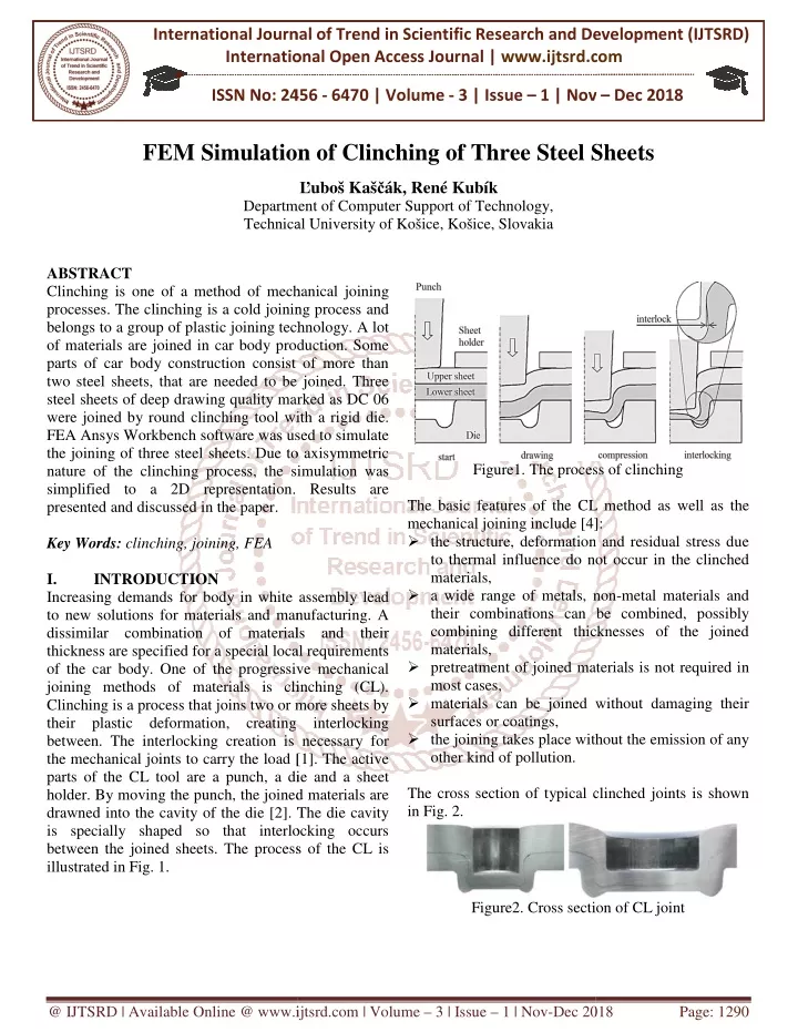
Clinching is one of a method of mechanical joining processes. The clinching is a cold joining process and belongs to a group of plastic joining technology. A lot of materials are joined in car body production. Some parts of car body construction consist of more than two steel sheets, that are needed to be joined. Three steel sheets of deep drawing quality marked as DC 06 were joined by round clinching tool with a rigid die. FEA Ansys Workbench software was used to simulate the joining of three steel sheets. Due to axisymmetric nature of the clinching process, the simulation was simplified to a 2D representation. Results are presented and discussed in the paper. Lubou00c5u00a1 Kau00c5u00a1cu00c3u00a1k | Renu00e9: Kubu00c3u00adk "FEM Simulation of Clinching of Three Steel Sheets" Published in International Journal of Trend in Scientific Research and Development (ijtsrd), ISSN: 2456-6470, Volume-3 | Issue-1 , December 2018, URL: https://www.ijtsrd.com/papers/ijtsrd20247.pdf Paper URL: https://www.ijtsrd.com/engineering/mechanical-engineering/20247/fem-simulation-of-clinching-of-three-steel-sheets/lubou0161-kau0161cu00e1k<br>

E N D
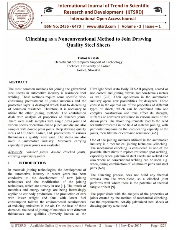
International Journal of Trend in International Open Access Journal International Open Access Journal | www.ijtsrd.com International Journal of Trend in Scientific Research and Development (IJTSRD) Research and Development (IJTSRD) www.ijtsrd.com ISSN No: 2456 ISSN No: 2456 - 6470 | Volume - 3 | Issue – 1 | Nov 1 | Nov – Dec 2018 FEM Simulation FEM Simulation of Clinching of Three Steel Sheets Three Steel Sheets Ľuboš Kaščák, René Kubík Department of Computer Support of Technology, Department Technical University Technical University of Košice, Košice, Slovakia ABSTRACT Clinching is one of a method of mechanical joining processes. The clinching is a cold joining process and belongs to a group of plastic joining technology. A lot of materials are joined in car body production. Some parts of car body construction consist of two steel sheets, that are needed to be joined. Three steel sheets of deep drawing quality marked as DC 06 were joined by round clinching tool with a rigid die. FEA Ansys Workbench software was used to simulate the joining of three steel sheets. Due to axisymmetric nature of the clinching process, the simulation was simplified to a 2D representation. Results are presented and discussed in the paper. Key Words: clinching, joining, FEA I. INTRODUCTION Increasing demands for body in white assembly lead to new solutions for materials and manufacturing. A dissimilar combination of materials and their thickness are specified for a special local of the car body. One of the progressive mechanical joining methods of materials is clinching (CL). Clinching is a process that joins two or more sheet their plastic deformation, creating between. The interlocking creation is n the mechanical joints to carry the load [1] parts of the CL tool are a punch, a die and holder. By moving the punch, the joined materials are drawned into the cavity of the die [2]. The die cavity is specially shaped so that interlocking occurs between the joined sheets. The process illustrated in Fig. 1. Clinching is one of a method of mechanical joining processes. The clinching is a cold joining process and belongs to a group of plastic joining technology. A lot of materials are joined in car body production. Some parts of car body construction consist of more than two steel sheets, that are needed to be joined. Three steel sheets of deep drawing quality marked as DC 06 were joined by round clinching tool with a rigid die. FEA Ansys Workbench software was used to simulate Due to axisymmetric Figure1. The process of clinching The process of clinching nature of the clinching process, the simulation was simplified to a 2D representation. Results are The basic features of the CL method as well as the mechanical joining include [4] ?the structure, deformation and residual stress due to thermal influence do not occur in the materials, ?a wide range of metals, non their combinations can be combined, possibly combining different thicknesses of the materials, ?pretreatment of joined materials is not required most cases, ?materials can be joined without damaging their surfaces or coatings, ?the joining takes place without the emission of any other kind of pollution. The cross section of typical clinched joints is shown in Fig. 2. The basic features of the CL method as well as the [4]: the structure, deformation and residual stress due to thermal influence do not occur in the clinched ide range of metals, non-metal materials and combinations can be combined, possibly combining different thicknesses of the joined Increasing demands for body in white assembly lead to new solutions for materials and manufacturing. A dissimilar combination of materials and their thickness are specified for a special local requirements One of the progressive mechanical materials is not required in linching (CL). two or more sheets by without damaging their their plastic deformation, creating interlocking . The interlocking creation is necessary for takes place without the emission of any load [1]. The active die and a sheet the joined materials are The die cavity t interlocking occurs process of the CL is clinched joints is shown Figure2. Cross section of CL joint Cross section of CL joint @ IJTSRD | Available Online @ www.ijtsrd.com www.ijtsrd.com | Volume – 3 | Issue – 1 | Nov-Dec 2018 Dec 2018 Page: 1290
International Journal of Trend in Scientific Research and Development (IJTSRD) ISSN: 2456 Trend in Scientific Research and Development (IJTSRD) ISSN: 2456 Trend in Scientific Research and Development (IJTSRD) ISSN: 2456-6470 II. The Anys Workbench 16 software was used for mathematical representation of the problem of joining of three steel sheets of DC 06 deep drawing The task was simplified on a 2D model because the tools and the joint itself are axially symmetrical. For this reason, the anisotropy of the joined not be considered in the calculation. A schematic representation of the input geomet the simulation model with the basic shown in Fig. 3. The figure shows limiting of simulation as well. All the degrees of freedom the nodal points of the die were removed did not move during the simulation. The nodal points of the punch elements can only be moved in the Y axis, with the punch making a vertical downward movement at a distance of 3.4 mm. The last boundary condition is a force of 400 N that acts o sheet holder to fix the joined materials during the simulation of the CL joining. Once the prescribed path has been reached, the punch performs a backward movement to the starting position while at the same time the force of the sheet holder ceases to act METHODOLOGY OF RESEARCH METHODOLOGY OF RESEARCH The Anys Workbench 16 software was used for mathematical representation of the problem of joining TableI. Input Data Of Material Model MaterialE [GPa]v [ DC 06 210 Input Data Of Material Model v [ - ]Rp0,2 [MPa] 0,3 0,3 142 deep drawing quality. The plastic part of the material model was modeled according to the Holomon hardening hardening exponent to the equation was determined experimentally, based on a standardized tensile test of the material DC 06. The Finite Element mesh consisted of PLANE 182 elements, i quadrangular elements, which are recommended for simulating 2D axis symmetric problems. The nodes of these elements have two degrees of freedom, which are displacements in each of the axes X and Y. The size of the elements in the mesh was 0.1 mm. In th case of processes such as clinching, where both the sheet and the finite element deformed, it is necessary to remesh certain intervals. This process remeshing. In this case, the deformation e criterion which, at defined intervals, controls the deformation energy of each element in the finite element mesh. If the deformation energy of the element exceeds the limits calculated adaptive remeshing process starts simulation consisted of forming the joint (step one) and returning the punch to the starting position together with the sheet holder The contacts between the tools and well as the contacts between the modeled as frictional contacts, using friction coefficients: between tool and sheet 0 sheets of 0.2. III. RESULTS AND DISCUSSION Fig. 4 shows the development of plastic deformation during the joining of three DC 06 sheets in the four characteristic bonding steps described in F The task was simplified on a 2D model because the tools and the joint itself are axially symmetrical. For The plastic part of the material model was modeled hardening law. The strain joined materials will exponent to the equation was determined experimentally, based on a standardized tensile test of A schematic representation of the input geometry of dimensions is limiting conditions for joined materials consisted of PLANE 182 elements, i.e. 2D quadrangular elements, which are recommended for symmetric problems. The nodes of these elements have two degrees of freedom, which are displacements in each of the axes X and Y. The size of the elements in the mesh was 0.1 mm. In the ll the degrees of freedom of of the die were removed, so that they did not move during the simulation. The nodal points of the punch elements can only be moved in the Y axis, with the punch making a vertical downward movement at a distance of 3.4 mm. The last boundary condition is a force of 400 N that acts on the body of linching, where both the sheet and the finite element mesh are significantly materials during the Once the prescribed path remesh the elements after certain intervals. This process is known as adaptive has been reached, the punch performs a backward movement to the starting position while at the same the deformation energy criterion which, at defined intervals, controls the deformation energy of each element in the finite . If the deformation energy of the calculated by the program, process starts. The two-step simulation consisted of forming the joint (step one) and returning the punch to the starting position ceases to act. (step two). ontacts between the tools and joined materials as the contacts between the joined materials were odeled as frictional contacts, using friction coefficients: between tool and sheet 0.12; between RESULTS AND DISCUSSION . 4 shows the development of plastic deformation during the joining of three DC 06 sheets in the four bonding steps described in Fig. 1. Figure3. The geometrical model and limiting conditions geometrical model and limiting The punch, die and sheet holder (Fig. 3 were modeled as perfectly stiff, non bodies. The joined sheets were modeled as deformable bodies, using a multilinear material model to describe the response of the joined material to the load. The input values for the material model of the materials in the form of steel sheets of the quality of DC 06 and thickness of 0.8 mm are given in nd thickness of 0.8 mm are given in Tab. I. . 3) in this case were modeled as perfectly stiff, non-deformable sheets were modeled as deformable bodies, using a multilinear material model material to the The input values for the material model of the joined materials in the form of steel sheets of the quality of Drawing @ IJTSRD | Available Online @ www.ijtsrd.com www.ijtsrd.com | Volume – 3 | Issue – 1 | Nov-Dec 2018 Dec 2018 Page: 1291
International Journal of Trend in Scientific Research and Development (IJTSRD) ISSN: 2456 Trend in Scientific Research and Development (IJTSRD) ISSN: 2456 Trend in Scientific Research and Development (IJTSRD) ISSN: 2456-6470 Compressio Compressio Figure5. Increase in plastic deformation in sheets during CL joint formation Increase in plastic deformation in sheets during CL joint formation Upsetting Upsetting Figure6. Increase in plastic deformation in sheets during CL joint formation during CL joint formation Increase in plastic deformation in sheets Fig. 6 shows a comparison of the between the real joint (left) and the joint resulting from the simulation. By comparing the characteristic areas of the two joints, such as the thickness of individual sheets, the thickness of the bottom of the joint or the interlocking between the so-called "S" shape of the sheets). Based on t comparison of the results, it is possible to state with certain tolerance that correspond to the result of the actual IV. Conclusion The paper presented the simulation of process of the three steel sheets quality DC 06 with the thickness of 0.8 mm. The simulation has been simplified into 2D conditions based on the axial symmetry of the entire joining process. The results of the simulation in the form of the representation of the plastic deformation in the sheets during the individual joining stages were presented, where a considerable plastic deformation of the upper sheet (on the punch side) was identified, which reduced to 6 times its thickness during joining process. The calculation was verified by showing the course of the reaction force acting on the punch during the formation of the comparison of the cross section of the real CL joint and the CL joint obtained by the simulation the results between the actual joining process and its simulation. a comparison of the cross sections the real joint (left) and the joint resulting from the simulation. By comparing the characteristic areas of the two joints, such as the thickness of individual sheets, the thickness of the bottom of the joint or the interlocking between the joined sheets (the called "S" shape of the sheets). Based on the visual results, it is possible to state with certain tolerance that correspond to the result of the actual joining process. Punch Punch Figure4. Increase in plastic deformation in sheets during CL joint formation during CL joint formation Increase in plastic deformation in sheets The 2D results were expanded by rotation to in the form of a 230 ° circle. For better visibility of the presented results, the finite element removed. The most critical area during the sheet metal on the punch side. The maximum plastic deformation during the joining in the area of the upper sheet at the point where it is excessively thinned. This area is known as the area of the neck of the joint and is considered the most critical in terms of the process of joining transfer. The course of the reaction force acting on the punch during the coupling is shown in Fig. 5. The graphs characterized by joining stages depending on the size of the joining force, where the shape of the materials is changed. It is possible to verify the simulation by comparing the magnitude of the joining force required to form the joint under realistic conditions with the reaction force acting on the punch during the joining. Another way to verify simulation is to compare its results with the results of a real joining process. The 2D results were expanded by rotation to 3D views in the form of a 230 ° circle. For better visibility of the presented results, the finite element mesh was removed. The most critical area during clinching is sheet metal on the punch side. The maximum the the simulation simulation results results is located just in the area of the upper sheet at the point where it is excessively thinned. This area is known as the area of the neck of the joint and is considered the most imulation of the clinching sheets of the deep drawing thickness of 0.8 mm. The joining and load simulation has been simplified into 2D conditions based on the axial symmetry of the entire joining eaction force acting on the punch . 5. The graphs is stages depending on the size simulation in the form of the representation of the plastic deformation in the sheets during the individual joining stages were presented, where a considerable plastic deformation of the upper sheet (on the punch side) was identified, imes its thickness during joining . The calculation was verified by showing the course of the reaction force acting on the punch during the formation of the clinched joint. The cross section of the real CL joint joint obtained by the simulation matched between the actual joining process and its of the joining force, where the shape of the joined t is possible to verify the omparing the magnitude of the joining force required to form the joint under realistic conditions with the reaction force acting on the punch . Another way to verify simulation is to compare its results with the results of a real-time @ IJTSRD | Available Online @ www.ijtsrd.com www.ijtsrd.com | Volume – 3 | Issue – 1 | Nov-Dec 2018 Dec 2018 Page: 1292
International Journal of Trend in Scientific Research and Development (IJTSRD) ISSN: 2456 Trend in Scientific Research and Development (IJTSRD) ISSN: 2456 Trend in Scientific Research and Development (IJTSRD) ISSN: 2456-6470 3.J. Mucha, and W. Witkowski, Joints Strength Analysis in the Aspects of Changes in the Forming Conditions,” Thin. Wall. Struct 66, 2014. 4.P. Groche, P. et al., “Joining by Forming review on joint mechanisms, applica future trends,” J. Mater. Process. Tech., vol pp. 1972 – 1994, 2014. 5.M. Israel, et al., “Thick Sheet Clinching Advanced Shipping and Ocean Engineering 2, pp. 1 – 10, 2013. ACKNOWLEDGMENT Author is grateful for the support of experimental works by project KEGA 065TUKE Innovation of educational process in CAD/CAM/CAE systems using computational cluster GRID. REFERENCES 1.P. Kamble, and R. Mahale, “Simulation and Parametric Study of Clinched Joint,” Eng. Tech., vol. 3, pp. 2730 – 2734, 2016. 2.F. Lambiase, “Mechanical Behaviour of Polymer Metal Hybrid Joints Produced by Clinching Using Different Tools,” Mater. Design., vol. 87, – 618, 2015. Witkowski, “The Clinching Author is grateful for the support of experimental Joints Strength Analysis in the Aspects of 065TUKE-4/2017 - education of using computational cluster Technology and Load Struct., vol. 82, pp. 55 – Joining by Forming - A review on joint mechanisms, applications and J. Mater. Process. Tech., vol. 10, P. Kamble, and R. Mahale, “Simulation and Parametric Study of Clinched Joint,” Int. Res. J. Thick Sheet Clinching,” 2734, 2016. Advanced Shipping and Ocean Engineering, vol. F. Lambiase, “Mechanical Behaviour of Polymer- Metal Hybrid Joints Produced by Clinching Using , vol. 87, pp. 606 @ IJTSRD | Available Online @ www.ijtsrd.com www.ijtsrd.com | Volume – 3 | Issue – 1 | Nov-Dec 2018 Dec 2018 Page: 1293