Download
1 / 7
80 likes | 96 Views
This paper presents how to design proportional integral controller and Fuzzy PI based controller for efficiently load frequency control. Loads on the electrical system always vary in relation to that time, which results in diversity of frequency, causing frequency control problems to be loaded. The frequency difference is highly undesirable and the maximum allowable difference in frequency is u00c2u00b1 0.5 Hz. This paper load frequency control is done by PI controller, which is a conventional controller. This type of controller is slow and the controller does not allow the designer to keep in mind the potential change in operating conditions and non linearity in the generator unit. To overcome these flaws, new intelligent controllers like Fuzzy PI Controller are presented to extinguish tie line power due to deviation in frequency and various load disturbances. The effectiveness of the proposed controller has been confirmed using the MATLAB SIMULINK software. The results show that the PI fuzzy controller provides fast response, little undershoots and negligible overshoot with small state transfer time to reach the final stable position. Ajay Kumar Maurya | Dr. G. K. Banerjee | Dr. Piush Kumar "Design Fuzzy-PI Based Controller for Load Frequency Control of Thermal - Thermal Area Interconnected Power System" Published in International Journal of Trend in Scientific Research and Development (ijtsrd), ISSN: 2456-6470, Volume-3 | Issue-1 , December 2018, URL: https://www.ijtsrd.com/papers/ijtsrd19164.pdf Paper URL: http://www.ijtsrd.com/engineering/electrical-engineering/19164/design-fuzzy-pi-based-controller-for-load-frequency-control-of-thermal---thermal-area-interconnected-power-system/ajay-kumar-maurya<br>

E N D
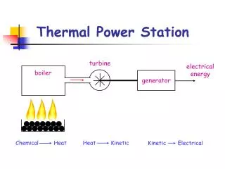
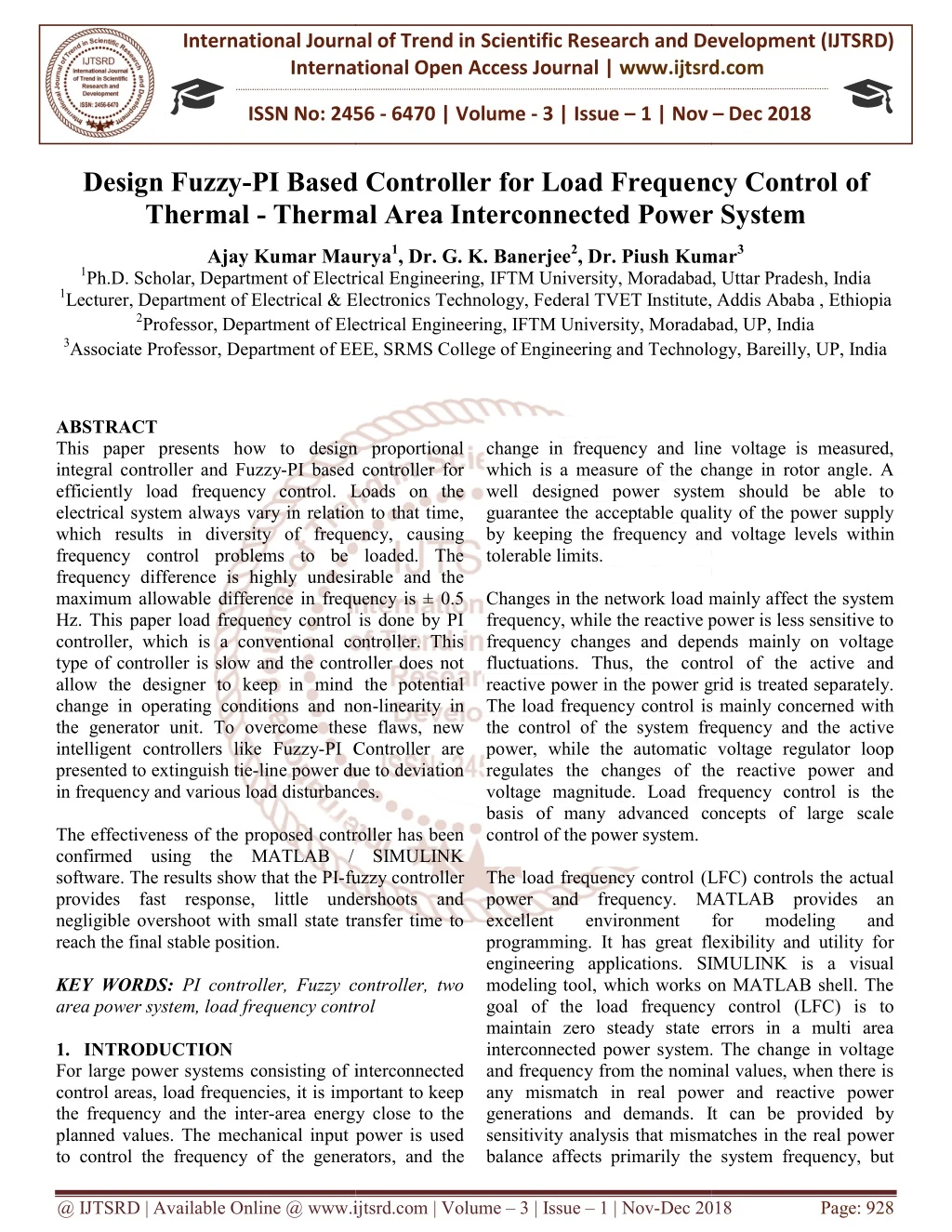
International Journal of Trend in International Open International Open Access Journal | www.ijtsrd.com International Journal of Trend in Scientific Research and Development (IJTSRD) Research and Development (IJTSRD) www.ijtsrd.com ISSN No: 2456 ISSN No: 2456 - 6470 | Volume - 3 | Issue – 1 | Nov 1 | Nov – Dec 2018 Design Fuzzy-PI Based Controller Thermal - Thermal Area Interconnected Power System Thermal Area Interconnected Power System Thermal Area Interconnected Power System PI Based Controller for Load Frequency Control or Load Frequency Control of Ajay Kumar Maurya Ajay Kumar Maurya1, Dr. G. K. Banerjee2, Dr. Piush Kumar Ph.D. Scholar, Department of Electrical Engineering, IFTM University, Moradabad, U ical & Electronics Technology, Federal TVET Institute, Addis Ababa , Ethiopia Professor, Department of Electrical Engineering, IFTM University, Moradabad, UP, India Department of EEE, SRMS College of Engineering and Technology, Bareilly, UP, India Department of EEE, SRMS College of Engineering and Technology, Bareilly, UP, India Dr. Piush Kumar3 versity, Moradabad, Uttar Pradesh, India Federal TVET Institute, Addis Ababa , Ethiopia 1Ph.D. Scholar, Department of Electrical Engineering, 1Lecturer, Department of Electrical & Electronics Technology, 2Professor, Department of Electrical Engineering, IFTM University, Moradabad, UP, India 3Associate Professor, Department of EEE, SRMS College of Engineering and Technology, Bareilly, UP, India Professor, Department of Electrical Engineering, IFTM University, Moradabad, UP, India ABSTRACT This paper presents how to design proportional integral controller and Fuzzy-PI based controller for efficiently load frequency control. Loads on the electrical system always vary in relation to that time, which results in diversity of frequency, causing frequency control problems to be loaded. The frequency difference is highly undesirable and the maximum allowable difference in frequency is ± 0.5 Hz. This paper load frequency control is done by PI controller, which is a conventional controller. This type of controller is slow and the controller does not allow the designer to keep in mind the potential change in operating conditions and non the generator unit. To overcome these flaws, new intelligent controllers like Fuzzy-PI Controller are presented to extinguish tie-line power due to deviation in frequency and various load disturbances. The effectiveness of the proposed controller has been confirmed using the MATLAB / SIMULINK software. The results show that the PI-fuzzy controller provides fast response, little undershoots and negligible overshoot with small state transfer time to reach the final stable position. KEY WORDS: PI controller, Fuzzy controller, two area power system, load frequency control 1.INTRODUCTION For large power systems consisting of interconnected control areas, load frequencies, it is important to keep the frequency and the inter-area energy close to the planned values. The mechanical input power is used to control the frequency of the generators to control the frequency of the generators, and the change in frequency and line voltage is measured, which is a measure of the change in rotor angle. A well designed power system should be able to guarantee the acceptable quality of the power supply by keeping the frequency and voltage levels tolerable limits. Changes in the network load mainly affect the system frequency, while the reactive power is less sensitive to frequency changes and depends mainly on voltage fluctuations. Thus, the control of the active and reactive power in the power grid is treated separately. The load frequency control is mainly concerned with the control of the system frequency and the active power, while the automatic voltage regulator loop regulates the changes of the reactive power and voltage magnitude. Load frequency control is the basis of many advanced concepts of large scale control of the power system. The load frequency control (LFC) controls the actual power and frequency. MATLAB provides an excellent environment programming. It has great flexibility and utility for engineering applications. SIMULINK is a visual modeling tool, which works on MATLAB shell. The goal of the load frequency control (LFC) is to maintain zero steady state errors in a multi area interconnected power system. and frequency from the nominal values, when there is any mismatch in real power and reactive power generations and demands. It can be provided by sensitivity analysis that mismatches in the real power balance affects primarily the sys balance affects primarily the system frequency, but This paper presents how to design proportional change in frequency and line voltage is measured, which is a measure of the change in rotor angle. A well designed power system should be able to guarantee the acceptable quality of the power supply by keeping the frequency and voltage levels within PI based controller for efficiently load frequency control. Loads on the electrical system always vary in relation to that time, which results in diversity of frequency, causing frequency control problems to be loaded. The frequency difference is highly undesirable and the m allowable difference in frequency is ± 0.5 This paper load frequency control is done by PI controller, which is a conventional controller. This type of controller is slow and the controller does not allow the designer to keep in mind the potential ange in operating conditions and non-linearity in the generator unit. To overcome these flaws, new Changes in the network load mainly affect the system frequency, while the reactive power is less sensitive to frequency changes and depends mainly on voltage fluctuations. Thus, the control of the active and power grid is treated separately. The load frequency control is mainly concerned with the control of the system frequency and the active power, while the automatic voltage regulator loop regulates the changes of the reactive power and ad frequency control is the basis of many advanced concepts of large scale PI Controller are line power due to deviation in frequency and various load disturbances. effectiveness of the proposed controller has been confirmed using the MATLAB / SIMULINK fuzzy controller The load frequency control (LFC) controls the actual provides fast response, little undershoots and negligible overshoot with small state transfer time to MATLAB provides an for modeling great flexibility and utility for and engineering applications. SIMULINK is a visual modeling tool, which works on MATLAB shell. The goal of the load frequency control (LFC) is to maintain zero steady state errors in a multi area interconnected power system. The change in voltage and frequency from the nominal values, when there is any mismatch in real power and reactive power generations and demands. It can be provided by sensitivity analysis that mismatches in the real power PI controller, Fuzzy controller, two area power system, load frequency control For large power systems consisting of interconnected control areas, load frequencies, it is important to keep area energy close to the planned values. The mechanical input power is used @ IJTSRD | Available Online @ www.ijtsrd.com www.ijtsrd.com | Volume – 3 | Issue – 1 | Nov-Dec 2018 Dec 2018 Page: 928
International Journal of Trend in Scientific Research and International Journal of Trend in Scientific Research and Development (IJTSRD) ISSN: 2456 Development (IJTSRD) ISSN: 2456-6470 leaves the bus voltage essentially unaffected. control system is essential to cancel the effects of the sudden load changes and to keep the frequency at the nominal value [3–5] 1.1 TWO-area power system model A two-area interconnected thermal power system as shown in Fig. 1 is considered. The system is widely used in literature for the design and analysis of AGC [7]. In Fig. 1, B1 and B2 are the frequency bias parameters; ACE1 and ACE2 are area control errors; X1 and X2 are the control outputs from the controller; R1 and R2 are the governor speed regulation parameters in p.u. Hz; TH1 and TH2 governor time constants in seconds; Δ are the governor output command (p.u.); are the turbine time constant in seconds; ΔPT 2 are the change in turbine output powers; and ΔPE2 are the load demand changes; are the power system gains; TP1 and TP2 system time constant in seconds; incremental change in tie line power (p.u.); Δf2 are the system frequency deviations in Hz. The relevant parameters are given in Appendix A. relevant parameters are given in Appendix A. leaves the bus voltage essentially unaffected. So, a control system is essential to cancel the effects of the sudden load changes and to keep the frequency at the For tiny deviation in the angles and the tie line changes with the power amount For tiny deviation in the angles and the tie line changes with the power amount V V P cos( x In accordance with the concept of "electrical stiffness" of synchronous machines, we define coefficient" of a line ?? = |??| |??| ? cos ( Thus the equation (2) can be written as 12 1 P T ( (2) 1 2 P cos( )( )( ) ) 12 12 1 1 2 2 1 1 2 2 In accordance with the concept of "electrical stiffness" of synchronous machines, we define "synchronizing area interconnected thermal power system as shown in Fig. 1 is considered. The system is widely used in literature for the design and analysis of AGC (?? − ?? ) (3) are the frequency bias are area control errors; Thus the equation (2) can be written as (4) o P T ( ) ) are the control outputs from the controller; are the governor speed regulation 12 1 2 2 are the speed ΔPH1 and ΔPH2 are the governor output command (p.u.); TT1 and TT 2 are the turbine time constant in seconds; ΔPT1 and are the change in turbine output powers; ΔPE1 are the load demand changes; KP1 and KP2 2 are the power system time constant in seconds; ΔPTieis the incremental change in tie line power (p.u.); Δf1 and are the system frequency deviations in Hz. The Figure 2: Conventional Two Area System: Basic Figure 2: Conventional Two Area System: Basic Block Diagram Block Diagram The frequency deviation is related to angle by the formula 1 d( f 2 or d( The frequency deviation is related to the reference 1 d( 2 ) ) ) 1 d( dt dt d ( ) ) 2 f dt t or 2 2 2 2 f d t 0 Thus the equation (3.4) can be written as Thus the equation (3.4) can be written as t t t t 2 T 2 T o P P f dt f dt f dt f dt 12 12 1 1 2 2 0 0 0 0 Taking Laplace transformation of equation Taking Laplace transformation of equation 2 T P (s) s The above equation can be represented as in figure (3) o (5) P (s) f (s) f (s) f (s) f (s) 12 12 1 1 2 2 The above equation can be represented as in figure (3) Figure 1: Two area Thermal–Thermal plant with conventional PI controller conventional PI controller Thermal plant with 1.2 Modeling of the tie-line The well known power transfer equation is V V P sin ( x Where 1 and 2 are the angles of end voltages V and V2 respectively. The sequence of subscript indicates that the tie line defines positive in power direction 1 to 2. Figure 3: Block Diagram Representation of a Tie Line Similarly the incremented tie line power expected from area 2 is given by 12 P (s) s Figure 3: Block Diagram Representation of a Tie – The well known power transfer equation is (1) 1 2 o ) 12 1 2 are the angles of end voltages V1 The sequence of subscript positive in power Similarly the incremented tie line power expected 2 T o P (s) f (s) f (s) f (s) f (s) 12 2 2 1 1 @ IJTSRD | Available Online @ www.ijtsrd.com www.ijtsrd.com | Volume – 3 | Issue – 1 | Nov-Dec 2018 Dec 2018 Page: 929
International Journal of Trend in Scientific Research and International Journal of Trend in Scientific Research and Development (IJTSRD) ISSN: 2456 Development (IJTSRD) ISSN: 2456-6470 The power balance equation for single area can be given by So for the double area, the equation should be modified as follows 2 T E o f T1 E1 12 P (s) P (s) P (s) T1 E1 12 P (s) P (s) P (s) The power balance equation for single area can be 0.15 So for the double area, the equation should be 0.1 Pu = 1.2 Ku = 1.467 0.05 Frequency Deviation (Hz.) H d ( f ) P P P P B B f f P P 1 1 0 1 1 1 1 1 1 1 1 1 2 1 2 d t 2H f (6) -0.05 s f (s) s f (s) 1 B B f (s) f (s) 1 1 1 1 1 1 o -0.1 If ???= ? ?? ? ? ?? ???????= ?? -0.15 Equation (6) can be written as f (s) P1 G (s) 1 Thus the complete block diagram representation of two area load frequency control is given in figure (1). 2.Ziegler -Nichols Rule Based Tuning For comparison the PID controller was tuned using conventional Ziegler –Nichols tuning rule based on the critical gain Ku and critical period P Ku and Pu were calculated from the sustained oscillations of the output by employing only proportional controller. The sustained oscillation response with proportional controller under critical gain is shown in Figure (4). As per the Ziegler Nichols rule the settings for PID controller parameter are given in the following table [1]. Controller parameters calculated for conventional controller are given in Table [2]. Table 1: Ziegler-Nichols tuning rules Type of control Gc(s) -0.2 f (s) G G (s) (s) P P (s) (s) P P (s) (s) P (s) P (s) 0 0.5 1 1.5 2 2.5 3 3.5 4 1 1 P1 K P1 T1 T1 E1 E1 12 12 Time (sec) Time (sec) P1 sT Figure 4: System response with proportional Figure 4: System response with proportional controller under critical gain controller under critical gain P1 Thus the complete block diagram representation of two area load frequency control is given in figure (1). Table 2: Controller Parameters for conventional controller Table 2: Controller Parameters for conventional controller Kc Nichols Rule Based Tuning For comparison the PID controller was tuned using Nichols tuning rule based on and critical period Pu. Values of were calculated from the sustained oscillations of the output by employing only nal controller. The sustained oscillation response with proportional controller under critical gain is shown in Figure (4). As per the Ziegler- Nichols rule the settings for PID controller parameter are given in the following table [1]. Controller s calculated for conventional controller are T Ki i Kc/Ti = 0.66 0.45.Ku= 0.66 Pu /1.2 = /1.2 = 1 3.Different types of controllers 3.1 PI - Controller The 'PI' controller will eliminate forced oscillations and steady state error, which will operation of the on-off controller and the 'P' controller, respectively. However, starting an integral mode has a negative impact on the response speed and overall stability of the system. Therefore, the PI controller does not increase the reaction rate. It can be expected because the PI controller has no means of predicting what will happen to the bug in the near future. This problem can be solved by introducing a derivative mode that is able to predict what will happen to the error in the near future and thus reduce it [13] 3.2 Fuzzy Controller The general architecture of a fuzzy controller is depicted in Figure (5) [14]. The origin of a fuzzy controller is an fuzzy inference engine (FIS), which includes fuzzification,, knowledge base evalu and defuzzification in the data flow. systems are the error and the change in the error of the feedback loop, while the output is the control action. There are 7 trapezoidal membership functions in each input i.e.NB (Negative Big), NM (Negative Medium), NS (Negative Small), Z (Zero), PS (Positive Small), PM (Positive Medium), PB (Positive Big). The mamdani rule base adopted mamdani rule base adopted Different types of controllers The 'PI' controller will eliminate forced oscillations and steady state error, which will result in the off controller and the 'P' controller, respectively. However, starting an integral mode has a negative impact on the response speed and overall stability of the system. Therefore, the PI controller does not increase the eaction rate. It can be expected because the PI controller has no means of predicting what will happen to the bug in the near future. This problem can be solved by introducing a derivative mode that is able to predict what will happen to the error in the ear future and thus reduce it [13] Nichols tuning rules K 0.5 K Ku Kc 0.5 Ti Td Proportional (P) Kc - - Proportional– Integral(PI) Proportional- Integral- Derivative (PID) 1.2 1 0.45K u P - K 1 0.45K c u sT i 1 P 2 P 8 0.6K K 1 sT u u 0.6K c d u sT i The general architecture of a fuzzy controller is depicted in Figure (5) [14]. The origin of a fuzzy controller is an fuzzy inference engine (FIS), which includes fuzzification,, knowledge base evaluation in the data flow. Theinputs to the systems are the error and the change in the error of the feedback loop, while the output is the control action. There are 7 trapezoidal membership functions in each NM (Negative Medium), NS (Negative Small), Z (Zero), PS (Positive Small), PM (Positive Medium), PB (Positive Big). The here here and and the the @ IJTSRD | Available Online @ www.ijtsrd.com www.ijtsrd.com | Volume – 3 | Issue – 1 | Nov-Dec 2018 Dec 2018 Page: 930
International Journal of Trend in Scientific Research and International Journal of Trend in Scientific Research and Development (IJTSRD) ISSN: 2456 Development (IJTSRD) ISSN: 2456-6470 defuzzification process is centroid method. The fuzzy rules are shown in Table [3]. defuzzification process is centroid method. The fuzzy attention and used automatically to adjust process variable is kept at the reference value. A FLC consists of three sections Namely, fuzzifier, rule base, and defuzzifier. The operator attention and used automatically to adjust some variables the process variable is kept reference value. A FLC consists of three sections Namely, fuzzifier, rule base, and defuzzifier. Fuzzy-PI controller structure is shown in Figure (6). controller structure is shown in Figure (6). Figure 6: PI-Fuzzy Logic controller in Simulink zzy Logic controller in Simulink 4.Results and Simulation Performed simulations using PI and Fuzzy controllers applied to a two area interconnected power systems. The developed system is simulated with 10 % step load disturbance in area 1. Due to this the change in dynamic responses of the system has been observed, as shown in below Figures. It is examine from the output responses that the proposed Fuzzy Controller is stable and less oscillations and the settling time also improved considerably. Also this output justified that this interconnection is valid for Thermal-Thermal systems. For conventional PI controller and Fuzzy-PI controller, the main objective is to improve the control performance 4.1 Uncontrolled case The frequency changes in area 10% step load perturbation is shown in figure (7). There is a steady state error in the response. There is a steady state error in the response. simulations using PI and Fuzzy-PI controllers applied to a two area interconnected power systems. The developed system is simulated with 10 % step load disturbance in area 1. Due to this the change in dynamic responses of the system has been hown in below Figures. It is examine from the output responses that the proposed Fuzzy-PI Controller is stable and less oscillations and the settling time also improved considerably. Also this output justified that this interconnection is valid for Thermal systems. For conventional PI PI controller, the main objective is to improve the control performance Figure 5: Structure of fuzzy logic controller Structure of fuzzy logic controller Table 3: Fuzzy Rule Base Table 3: Fuzzy Rule Base E ∆E NB NM PB PM PM PM NS PM PM ZE NS NS PS ZE NS PM NS NS NM NM NM PB NS NM NB NB NB NB NM NS ZE PS PM PB PB PB PB PB PM PS PS PS NS PM PS PS PS NM NM NB NB NB NB PS PS ZE PS PS NS NS PS ZE NS A fuzzy system is described by a set of IF rules and uses diverse membership functions. To solve the load-frequency control problem in fuzzy controller, controller inputs are Area Control Error and derivative of Area Control Error and its considered as the control signal. The member ship function uses in fuzzy logic controller for Error, change in Error and output is shown in figure (5). A fuzzy system is described by a set of IF-THEN rules and uses diverse membership functions. To frequency control problem in fuzzy controller, controller inputs are Area Control Error and derivative of Area Control Error and its output are considered as the control signal. The member ship function uses in fuzzy logic controller for Error, change in Error and output is shown in figure (5). The frequency changes in area-1 and area-2 for the 10% step load perturbation is shown in figure (7). Figure 7: Two area Thermal (Uncontrolled) with a disturbance of area-1: Frequency deviation of area 4.2 Controlled Case with Proportional plus Integral Controller The frequency changes in area 10% step load perturbation is shown in figure (8) and (9). (10% step load perturbation is given in area (9). (10% step load perturbation is given in area -1). Two area Thermal-Thermal plant disturbance of 10 % in 1: Frequency deviation of area -1 and area – 2 Figure 5: Membership functions of inputs (E, and output Membership functions of inputs (E, ΔE) Controlled Case with Proportional plus 3.3 PI- Fuzzy Logic Controller A Fuzzy-PI controller designed based on a linear model of power system under the loading condition FLC designed to eliminate the need for continuous FLC designed to eliminate the need for continuous The frequency changes in area-1 and area-2 for the 10% step load perturbation is shown in figure (8) and PI controller designed based on a linear model of power system under the loading condition @ IJTSRD | Available Online @ www.ijtsrd.com www.ijtsrd.com | Volume – 3 | Issue – 1 | Nov-Dec 2018 Dec 2018 Page: 931
International Journal of Trend in Scientific Research and International Journal of Trend in Scientific Research and Development (IJTSRD) ISSN: 2456 Development (IJTSRD) ISSN: 2456-6470 The steady state error is zero in this case. The frequency deviation of area-1 is much more The steady state error is zero in this case. The 1 is much more Figure 10: Two area Thermal (Controlled with Fuzzy-PI) With disturbance of 10 % in area-1: Frequency deviation of area 1: Frequency deviation of area -1 Figure 10: Two area Thermal-Thermal plant With disturbance of 10 Figure 8: Two area Thermal-Thermal plant (Controlled with PI) with Disturbance of 10 % in area-1: Frequency deviation of area 1: Frequency deviation of area -1 Thermal plant Disturbance of 10 % in Area 2 PI Controller 0 -0.01 -0.02 -0.03 -0.04 -0.05 -0.06 -0.07 0 5 10 15 20 25 30 35 40 45 50 Figure 11: Two area Thermal (Controlled with Fuzzy-PI) With Disturbance of 10 % in area-1: Frequency deviation of area 4.4 Comparison between PI and Fuzzy Controller wo area Thermal-Thermal plant With Disturbance of 10 1: Frequency deviation of area -2 Comparison between PI and Fuzzy-PI Time (Second) Figure 9: Two area Thermal-Thermal plant (Controlled with PI) with a Disturbance of 10 % in area-1: Frequency deviation of ar 4.3 Controlled Case with Fuzzy-PI Controller The frequency changes in area-1 and area 10% step load perturbation is shown in figure (10) and (11). (10% step load perturbation is given in The steady state error is zero in this case. The frequency deviation of area-1 is much more Thermal plant Disturbance of 10 % in 1: Frequency deviation of area -2 PI Controller 1 and area-2 for the 10% step load perturbation is shown in figure (10) and (11). (10% step load perturbation is given in area -1). The steady state error is zero in this case. The 1 is much more Figure 12: Comparison result between Fuzzy-PI Disturbance of 10 % in Figure 12: Comparison result between Fuzzy and PI controller with Disturban area-1: Frequency deviation of area 1: Frequency deviation of area -1 @ IJTSRD | Available Online @ www.ijtsrd.com www.ijtsrd.com | Volume – 3 | Issue – 1 | Nov-Dec 2018 Dec 2018 Page: 932
International Journal of Trend in Scientific Research and International Journal of Trend in Scientific Research and Development (IJTSRD) ISSN: 2456 Development (IJTSRD) ISSN: 2456-6470 performance in term of settling time and overshoot of PI controller is better. There is no steady state PI controller shows its effectiveness over the conventional PI controller. performance in term of settling time and overshoot of fuzzy-PI controller is better. There is no steady state error. So fuzzy-PI controller shows its effectiveness over the conventional PI controller. The result shows that the proposed intelligent controller is having improved dynamic response and at the same time faster than conventional APPENDIX Parameter KP1 = KP2 120 Hz. / p.u. MW KH1 =KH2 1 Hz. / p.u. MW KT1 =KT2 1 Hz. / p.u. MW TP1 = TP2 TH1 =TH2 TT1 = TT2 B1 = B2 0.425 p.u. MW / Hz. R1 = R2 2.4 Hz. / p.u. MW To 0.0867 p.u. MW/Hz References 1.O.I. Elgerd, Electric Energy Systems Theory Introduction, second ed., Tata McGraw Hill, New Delhi, 2000. hat the proposed intelligent controller is having improved dynamic response and at the same time faster than conventional controller Value 120 Hz. / p.u. MW 1 Hz. / p.u. MW 1 Hz. / p.u. MW 20 Sec. Figure 13: Comparison result between Fuzzy and PI controller in with Disturbance of 10 % in area-1: Frequency deviation of area 1: Frequency deviation of area -2 Figure 13: Comparison result between Fuzzy-PI Disturbance of 10 % in The comparison of peak undershoots; Peak Overshoot and Settling Time via PI controller and Fuzzy controller are given in Table [3]. Table 3: Thermal-Thermal plant: PI Controller Vs Fuzzy-PI Controller Peak Undershoot 0.08 Sec. 0.08 Sec. 0.3 Sec. The comparison of peak undershoots; Peak Overshoot and Settling Time via PI controller and Fuzzy-PI 0.425 p.u. MW / Hz. 2.4 Hz. / p.u. MW 0.0867 p.u. MW/Hz Thermal plant: PI Controller Vs Peak Overshoot Settling Time(Sec) O.I. Elgerd, Electric Energy Systems Theory – An Introduction, second ed., Tata McGraw Hill, New Two Area PI Control ler PI- Fuzzy Control ler Area -1 - 0.15 57 Area -2 - 0.06 29 Area -1 Area -2 Are a-1 Are a-2 2.P. Kundur, Power System Stability and Control, eighth reprint, Tata McGraw Hill, New Delhi, 2009. Kundur, Power System Stability and Control, eighth reprint, Tata McGraw Hill, New Delhi, 0.02 97 0.00 03 12.8 8 14.8 5 3.H. Bevrani, Robust Power System Frequency Control, Springer, New York, 2009. Control, Springer, New York, 2009. H. Bevrani, Robust Power System Frequency - - 0.00 27 0.00 00 0.13 20 0.05 62 7.25 8.55 4.I.P. Kumar, D.P. Kothari, Recent philosophies of automatic generation control strate systems, IEEE Trans. Power Syst. 20 (2005) 346 357. I.P. Kumar, D.P. Kothari, Recent philosophies of automatic generation control strategies in power systems, IEEE Trans. Power Syst. 20 (2005) 346– 5.Conclusion In this paper a new technique Fuzzy-PI controller is designed for automatic load frequency control of interconnected Thermal - Thermal systems. The controller performances Fuzzy-PI approach is in work for a Load Frequency Control for Generation of Interconnected Power System. controller can handle the non-linearity and at the same time faster than other conventional controllers. Also the simulation results are compared with a conventional other controller. From the Result shown in figure (8) to figure (13). The results obtained for double area Thermal-Thermal plant shows the superiority such controllers over the conventional PI controllers. In Fuzzy-PI Controller the settling time has been reduced in area1 and area 2 are 5.63 sec and 6.30 sec respectively. It is explicit that the spectively. It is explicit that the PI controller is 5.H. Shayaghi, H.A. Shayanfar, A. Jalili, Load frequency control strategies: a state of the art survey for the researcher, Energy Convers. Manag. 50 (2009) 344–354. 354. H. Shayaghi, H.A. Shayanfar, A. Jalili, Load frequency control strategies: a state of the art survey for the researcher, Energy Convers. designed for automatic load frequency control of Thermal systems. The PI approach is in work for a Load Frequency Control for Generation of nected Power System. 6.K.P.S. Parmar, S. Majhi, D. frequency control of a realistic power system with multi-source power generation, Int. J. Electr. Power Energy Syst. 42 (2012) 426 Power Energy Syst. 42 (2012) 426–433. K.P.S. Parmar, S. Majhi, D.P. Kothari, Load frequency control of a realistic power system with source power generation, Int. J. Electr. The The proposed proposed linearity and at the same time faster than other conventional controllers. Also the simulation results are compared with a conventional other controller. From the Result shown figure (13). The results obtained for Thermal plant shows the superiority such controllers over the conventional PI PI Controller the settling time has been reduced in area1 and area 2 are 5.63 sec and 7.U.K. Rout, R.K. Sahu, S. Panda, Design and analysis of differential evolution algorithm based automatic generation control for interconnected power system, Ain Shams Eng. J. 4 (3) (2013) 409–421. U.K. Rout, R.K. Sahu, S. Panda, Design and analysis of differential evolution algorithm based generation control for interconnected power system, Ain Shams Eng. J. 4 (3) (2013) 8.M. Masiala, M. Ghribi and A. Kaddouri, Senior Member,“An Adaptive Fuzzy Controller Gain “An Adaptive Fuzzy Controller Gain M. Masiala, M. Ghribi and A. Kaddouri, Senior @ IJTSRD | Available Online @ www.ijtsrd.com www.ijtsrd.com | Volume – 3 | Issue – 1 | Nov-Dec 2018 Dec 2018 Page: 933
International Journal of Trend in Scientific Research and International Journal of Trend in Scientific Research and Development (IJTSRD) ISSN: 2456 Development (IJTSRD) ISSN: 2456-6470 14.Sateesh Machavarapu Suman , Load Frequency Control of Two Area Interconnected Power System Using Conventional and Intelligent Controllers, Journal of Engineering Applications, ISSN : 2248 Version 3), January 2014, pp.156 2014, pp.156-160 Scheduling For Power System Load Control” Dept. University de Moncton, New Brunswick, Canada 1515 -1520, IEEE International Conference on Industrial Technology (ICIT), 2004 Scheduling For Power System Load -- Frequency Sateesh Machavarapu Suman , Load Frequency Control of Two Area Interconnected Power System Using Conventional and Intelligent Controllers, Int. Journal of Engineering Applications, ISSN : 2248-9622, Vol. 4, Issue 1( Kumar Kumar Vavilala, Vavilala, R S Srinivas, of Electrical Engineering, University de Moncton, New Brunswick, Canada IEEE International Conference on Research Research and and 9.N. Jaleeli, D. N. Ewart, and L. H. Fink. “Understanding Automtic Generation Control.” IEEE Transactionson Power Systems, No.3. August 1992, pp.1106-1122 and L. H. Fink. “Understanding Automtic Generation Control.” 15.J. Nanda and B. L. Kaul, "Automatic generation control of an interconnected power system", IEE, Vol 125, No. 5, 1978, pp. 385 Vol 125, No. 5, 1978, pp. 385-390 Systems,Vol. 7. L. Kaul, "Automatic generation control of an interconnected power system", Proc. 10.L.C. Saikia, J. Nanda, S. Mishra, Performance comparison of several classical controllers in AGC for multi-area interconnected thermal system, Int. J. Electr. Power Energy Syst. 33 (2011) 394–401. L.C. Saikia, J. Nanda, S. Mishra, Performance comparison of several classical controllers in area interconnected thermal system, Int. J. Electr. Power Energy Syst. 33 16.Nilay.N.Shah, Aditya. D. Chafekar and Dwij. N.Mehta, “Automatic Load Frequency Control of Two Area Power System With Conventional and Fuzzy Logic Control” International Journal of Research in Engineering and Technology, Volume 1, Issue 3 ,Nov. 2012, pp. 343 1, Issue 3 ,Nov. 2012, pp. 343-347. Nilay.N.Shah, Aditya. D. Chafekar and Dwij. N.Mehta, “Automatic Load Frequency Control of r System With Conventional and Fuzzy Logic Control” International Journal of Research in Engineering and Technology, Volume 11.S.A. Taher, M.H. Fini, S.F. Aliabadi, Fractional order PID controller design for LFC in electric power systems using imperialist competitive algorithm, Ain Shams Eng. J. 5 (2014) 121 algorithm, Ain Shams Eng. J. 5 (2014) 121–135. , M.H. Fini, S.F. Aliabadi, Fractional order PID controller design for LFC in electric power systems using imperialist competitive 17.Saravuth Pothiya, Issarachai Ngamroo, Suwan Runggeratigul, and Prinya Tantaswadi, “Design of Optimal Fuzzy Logic based PI Controller using Multiple Tabu Search Algorithm for Load Frequency Control” International Journal of Control, Automation, and Systems, vol. 4, no. 2, pp. 155-164, April 2006 Saravuth Pothiya, Issarachai Ngamroo, Suwan Runggeratigul, and Prinya Tantaswadi, “Design of imal Fuzzy Logic based PI Controller using Multiple Tabu Search Algorithm for Load International Journal of Control, Automation, and Systems, vol. 4, no. 2, 12.Ramanand Kashyap, Prof. S.S. Sankeswari, Prof. B. A. Patil ,Load Frequency Control Using Fuzzy PI Controller Generation of Interconnected Hydro Power System ,International Journal of Emerging Technology and Advanced Engineering, Volume 3, Issue 9, September 2013 Ramanand Kashyap, Prof. S.S. Sankeswari, Prof. trol Using Fuzzy- PI Controller Generation of Interconnected Hydro International Journal of Emerging Technology and Advanced Engineering, Volume 18.Xiangping Meng, Qingxian Gong, Lei Feng, Wen Zheng, Weijun Zhang, “PI Fuzzy Sliding Mode Load Frequency. Control Interconnected Power International Symposium on Houston Texas, pp. 1023-1027, Xiangping Meng, Qingxian Gong, Lei Feng, Wen un Zhang, “PI Fuzzy Sliding Mode Load Frequency. Control Interconnected Power Symposium on Intelligent Control 13.Vasadi Srinivasa Rao, P. D. Srinivas, CH. Ravi Kumar, Load Frequency Control (LFC) of Three Area Interconnected Adaptive Neuro Fuzzy International Journal of Scientific Engineering and Technology Research Vol.04,Issue.43, October-2015, Pages:9482 Vasadi Srinivasa Rao, P. D. Srinivas, CH. Ravi of of Multiarea Multiarea IEEE IEEE ntrol (LFC) of Three Systems” Systems” Area Adaptive International Journal of Scientific Engineering and Technology Research Interconnected Neuro Power Power System System using System, System, using Fuzzy Interface Interface 1027, October 2003 ISSN ISSN 2319 2319-8885 2015, Pages:9482-9488 @ IJTSRD | Available Online @ www.ijtsrd.com www.ijtsrd.com | Volume – 3 | Issue – 1 | Nov-Dec 2018 Dec 2018 Page: 934