Download
1 / 5
50 likes | 52 Views
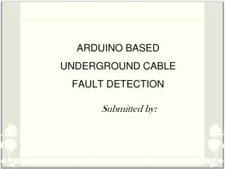
This paper presents a device to detect the vehicle's speed and recording the image. The major cause of road accident is mostly caused by human speed. The speed of a moving vehicle is determined by using calculation from a particular distance and time as an approach to estimate the vehicle speed. This system is designed to reduce the road accidents in the development of the vehicle speed detector system by using an IR sensor, Camera, 16x2 LCD, buzzer, LED and Arduino UNO. Police stations handle this system for reducing the vehicle's accidents conditions. In this system, two IR LED's transmitter and receiver sensor pairs, which are installed on the highway 27 cm apart, with the transmitter and the receiver of each pair on the same side of the road. The system displays the time taken by the vehicle in crossing the distance from one pair to the other from which the speed of the vehicle is calculated. If a vehicle exceeds the speed limit then LED is ON while the buzzing sound gives an indication to the police stations. The camera is used for recording the vehicle's images and LCD is used to display the vehicle's speed. Arduino UNO is the heart of the system, which controls all the function of the circuit. Ni Ni San Hlaing | Lae Yin Mon "Arduino Based Vehicle Abnormal Behavior Detection System using Camera with SD Card" Published in International Journal of Trend in Scientific Research and Development (ijtsrd), ISSN: 2456-6470, Volume-3 | Issue-5 , August 2019, URL: https://www.ijtsrd.com/papers/ijtsrd26519.pdf Paper URL: https://www.ijtsrd.com/engineering/electronics-and-communication-engineering/26519/arduino-based-vehicle-abnormal-behavior-detection-system-using-camera-with-sd-card/ni-ni-san-hlaing<br>

E N D
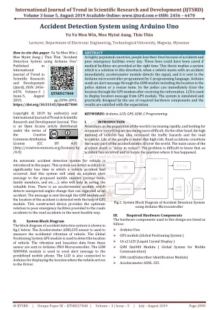
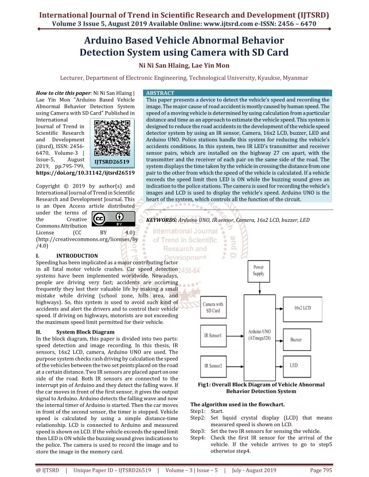
International Journal of Trend in Scientific Research and Development (IJTSRD) Volume 3 Issue 5, August 2019 Available Online: www.ijtsrd.com e-ISSN: 2456 – 6470 Arduino Based Vehicle Abnormal Behavior Detection System using Camera with SD Card Ni Ni San Hlaing, Lae Yin Mon Lecturer, Department of Electronic Engineering, Technological University, Kyaukse, Myanmar How to cite this paper: Ni Ni San Hlaing | Lae Yin Mon "Arduino Based Vehicle Abnormal Behavior Detection System using Camera with SD Card" Published in International Journal of Trend in Scientific Research and Development (ijtsrd), ISSN: 2456- 6470, Volume-3 | Issue-5, August 2019, pp.795-799, https://doi.org/10.31142/ijtsrd26519 Copyright © 2019 by author(s) and International Journal of Trend in Scientific Research and Development Journal. This is an Open Access article distributed under the terms of the Creative Commons Attribution License (CC (http://creativecommons.org/licenses/by /4.0) I. INTRODUCTION Speeding has been implicated as a major contributing factor in all fatal motor vehicle crashes. Car speed detection systems have been implemented worldwide. Nowadays, people are driving very fast; accidents are occurring frequently they lost their valuable life by making a small mistake while driving (school zone, hills area, and highways). So, this system is used to avoid such kind of accidents and alert the drivers and to control their vehicle speed. If driving on highways, motorists are not exceeding the maximum speed limit permitted for their vehicle. II. System Block Diagram In the block diagram, this paper is divided into two parts: speed detection and image recording. In this thesis, IR sensors, 16x2 LCD, camera, Arduino UNO are used. The purpose system checks rash driving by calculation the speed of the vehicles between the two set points placed on the road at a certain distance. Two IR sensors are placed apart on one side of the road. Both IR sensors are connected to the interrupt pin of Arduino and they detect the falling wave. If the car moves in front of the first sensor, it gives the output signal to Arduino. Arduino detects the falling wave and now the internal timer of Arduino is started. Then the car moves in front of the second sensor, the timer is stopped. Vehicle speed is calculated by using a simple distance-time relationship. LCD is connected to Arduino and measured speed is shown on LCD. If the vehicle exceeds the speed limit then LED is ON while the buzzing sound gives indications to the police. The camera is used to record the image and to store the image in the memory card. ABSTRACT This paper presents a device to detect the vehicle’s speed and recording the image. The major cause of road accident is mostly caused by human speed. The speed of a moving vehicle is determined by using calculation from a particular distance and time as an approach to estimate the vehicle speed. This system is designed to reduce the road accidents in the development of the vehicle speed detector system by using an IR sensor, Camera, 16x2 LCD, buzzer, LED and Arduino UNO. Police stations handle this system for reducing the vehicle’s accidents conditions. In this system, two IR LED’s transmitter and receiver sensor pairs, which are installed on the highway 27 cm apart, with the transmitter and the receiver of each pair on the same side of the road. The system displays the time taken by the vehicle in crossing the distance from one pair to the other from which the speed of the vehicle is calculated. If a vehicle exceeds the speed limit then LED is ON while the buzzing sound gives an indication to the police stations. The camera is used for recording the vehicle’s images and LCD is used to display the vehicle’s speed. Arduino UNO is the heart of the system, which controls all the function of the circuit. KEYWORDS: Arduino UNO, IR sensor, Camera, 16x2 LCD, buzzer, LED IJTSRD26519 BY 4.0) Fig1: Overall Block Diagram of Vehicle Abnormal Behavior Detection System The algorithm used in the flowchart. Step1: Start. Step2: Set liquid crystal display (LCD) that means measured speed is shown on LCD. Step3: Set the two IR sensors for sensing the vehicle. Step4: Check the first IR sensor for the arrival of the vehicle. If the vehicle arrives to go to step5 otherwise step4. @ IJTSRD | Unique Paper ID – IJTSRD26519 | Volume – 3 | Issue – 5 | July - August 2019 Page 795
International Journal of Trend in Scientific Research and Development (IJTSRD) @ www.ijtsrd.com eISSN: 2456-6470 Step5: Get the first IR sensor time in millis. Step6: Check the second IR sensor for the arrival of the vehicle. If the vehicle arrives to go to step7 otherwise step6. Step7: Get the second IR sensor time in millis. Step8: Check the first IR sensor time and the second IR sensor time are not equal to zero. If the IR sensors times are not equal to zero go to step9 otherwise print “OK” on LCD and step4. Step9: Check the time1 greater than the time2. If the time1 greater than the time2 go to step10, step12 and step13 otherwise step11. Step10: Subtraction the time1 and the time2. Step11: Subtraction the time2 and the time1. Step12: Calculate the speed of the vehicles in cm/s. Step13: Convert the speed of the vehicle from cm/s to km/h. Step14: Check the speed of the vehicle greater than 8 km/h. If the speed of the vehicle greater than the 8 km/h go to step15 otherwise step16. Step15: Print speed value on LCD and Buzzer and LED ON for 3 seconds. Step16: Print speed value on LCD for 3 seconds. Step17: Go to step4. Step18: Exit. III. A.Software Implementation for IR Sensor The software programming language for the IR sensor is very simple. The setup function will follow the declaration of IR pins are input by using to set pinMode. pinMode(2, INPUT); pinMode(3, INPUT); The loop function includes the code to be executed continuously reading the IR pins. Firstly, check the first IR sensor for the arrival of the vehicle. If the vehicle is arrived the time1 get in millisec. Moreover, check the second IR sensor for the arrival of the vehicle. If the vehicle arrives the time 2 gets in millisec. if (digitalRead(2)==0) first_sensor_time=millis(); if (digitalRead(3)==0) second_sensor_time=millis(); B.Software Implementation for Code Explanation of VehicleAbnormal Behavior Detector Sketch At the beginning of the code a header file is declared by name LiquidCrystal.h which is used for the LCD display. In the next line pins of LCD are declared in the function “Liquid Crystal Display (LCD) (4, 5, 6, 7, 8, 9)”, number in the bracket shows the pins of Arduino pins that are connected to the LCD. Inline 3 and 2 two integers are declared by the name sensor1 and sensor2, these are pins of Arduino that are connected to the IR sensors. After it 4 integers are declared by the name first sensor time, second sensor time, difference and float second1, second2. Where the first sensor time is the measured time if sensor1 is activated and the second sensor time is the measured time if sensor2 is activated. The difference is the difference of first sensor time and second sensor time, which is equivalent to the time taken by car to go from sensor1 to sensor2 or sensor2 to sensor1. The float is declared by name second1 and second2 that is measured the time from the sensors. Now double is declared by name speed that is the measured speed of the running car. And then, inline 10 and 11 two integers are declared by the name of buzzer and LED, these are pins of Arduino that are connected to the buzzer and LED.In the void setup( ) function, LCD is being by using lcd.begin(16,2) function. LCD is cleared by using the lcd.clear( ) function and SPEED MEASUREMENT is printed on LCD by using the function “LCD.print”. After it 4 integers are declared by the name pinMode(2, INPUT), pinMode(3, INPUT), pinMode(buzzer, OUTPUT)and pinMode(light, OUTPUT). First IR sensor is declared input by using the pinMode(3, INPUT) function and second IR sensor is declared input by using the pinMode(2, INPUT) function. The buzzer is declared output by using the pinMode(buzzer, OUTPUT) function and LED is declared output by using the pinMode(light, OUTPUT) function. In the void loop( ) function, “if”, “else if” and “else conditions” are used for checking. Firstly, checking a first IR sensor is high by using “if” condition and if the first IR sensor is high get time in millisec. Checking the second IR sensor is high by using “if” condition and if the second IR sensor is high get time in millisec. Secondly, checking first sensor time and second sensor time is not equal to zero by using “if” condition. If the first sensor time and second sensor time are not equal to zero, checking first sensor time greater than the second sensor time by using “if” condition. If the first sensor time greater than the second sensor time, first sensor time subtract the second sensor time in the difference and Implementation Fig 2: Flowchart of Vehicle Abnormal Behavior Detection System @ IJTSRD | Unique Paper ID – IJTSRD26519 | Volume – 3 | Issue – 5 | July - August 2019 Page 796
International Journal of Trend in Scientific Research and Development (IJTSRD) @ www.ijtsrd.com eISSN: 2456-6470 calculate the speed in the distance and time relationship formula. Speed convert (cm/s) to (km/h). Checking second sensor time greater than the first sensor time by using “else if” condition. If the second sensor time greater than the first sensor time, second sensor time subtract the first sensor time in the difference. Speed is printed on LCD by using lcd.print function. Checking speed greater than the defined speed by using “if” condition. If speed greater than the defined speed, buzzer and LED are high. If speed less than the defined speed by using “else” condition, buzzer and LED are low. If the first sensor time and second sensor time are equal to zero by using “else” condition, OK is printed on LCD by using lcd.print function. C.Hardware Implementation for Circuit Diagram of Vehicle Abnormal Behavior Detection System corresponding gives the speed. Now vehicle’s speed is calculated by using a simple time-distance relationship. This system speed is calculated in cm/s. And then, speed cm/s convert speed km/h by using the formula. LCD is connected to the Arduino and measured speed is shown on the LCD display. If the vehicle exceeds the speed limit then the LED gets ON while the buzzing sound gives an indication to the polices that the vehicle is crossing the speed limits. The camera is used to capture the video recording of that vehicle between both IR sensors. The camera includes the SD card for storing the video recording. D.Hardware Implementation for Vehicle Abnormal Behavior Detector Process Fig 4: Vehicle Abnormal Behavior Detector Process Figure 4: show vehicle abnormal behavior detector process. In this process, two IR sensors are used to detect the vehicle for getting time between the two IR sensors. If the first IR sensor arrives the vehicle, it gets time in millisec. And then, if the second IR sensor also arrives the vehicle, it gets time in millisec. Checking first sensor time and second sensor time is not equal to zero. If the first sensor time and second sensor time are not equal to zero and if first sensor time greater than the second sensor time, first sensor time subtract the second sensor time in the difference. If the second sensor time greater than the first sensor time, second sensor time subtract first sensor time indifference. And then, speed is calculated in the distance and time relationship formula. After it, speed (cm/s) convert to speed (km/h). Speed (km/h) printed on LCD. If speed greater than the defined speed, buzzer and LED ON. This process is ending. E. Speed measurement of vehicle abnormal behavior detector system This system comprises two IR sensor pairs, which are installed apart on one side of the road. The system displays the time taken by the vehicle in crossing this 10 cm distance from one pair to the other with delay time is 200 millisec from which the speed of the vehicle is calculated as follows; Fig 3: Overall Circuit Diagram of the system This circuit is constructed with three main sections. The first section is IR sensors which are the input section. The second one is LCD which is the output section. And the last one is the microcontroller Arduino UNO. Two IR sensors are placed together apart on one side of the road. The system basically comprises two IR LED’s transmitter and receiver sensor pairs, which are installed on the highway 27 cm apart, with the transmitter and the receiver of each pair on the same side of the road. Using the timer, select the speed limit 8 km/h for the restriction area. The system displays the time taken by the vehicle in crossing the distance from one pair to the other from which the speed of the vehicle is calculated. Arduino UNO is the heart of the system, which controls all the function of the circuit. If the vehicle arrives at the first IR sensor, the first sensor senses this coming vehicle. The first IR sensor gets a signal. This signal sends to the microcontroller. Arduino detects the falling waves and now internal timer of Arduino is started. Then the vehicle is crossing in front of the second sensor, the timer is stopped. Both IR sensors are connected to the interrupt pin of Arduino, and they detect the falling wave. The microcontroller is programmed by using C programming that calculates the time duration between two sensors, @ IJTSRD | Unique Paper ID – IJTSRD26519 | Volume – 3 | Issue – 5 | July - August 2019 Page 797
International Journal of Trend in Scientific Research and Development (IJTSRD) @ www.ijtsrd.com eISSN: 2456-6470 Speed = Equation (1) Distance Delay Time = 200 millisec Speed (cm/s) = (10 1000)/200 = 50 cm/s Speed (km/h) = Speed (cm/s) = 1.8 km/h The speed of the vehicle is 1.8 km/h. In this saturation, the buzzer and LED are not alarmed. The distance between two sensors is 27 cm and delay time is 30 millisec from which the speed of the vehicle is calculated as follows; Distance = 27 cm Delay Time = 30 millisec = 30 10-3 sec Speed (cm/s) = (27 1000)/30 = 900 cm/s Speed (km/h) = Speed (cm/s) 0.036 = 32.4 km/h The speed of the vehicle is 32.4 km/h. In this saturation, the buzzer and LED are alarmed to the police station. The distance between two sensors is 30 cm and delay time is 15 millisecond from which the speed of the vehicle is calculated as follows; Distance = 30 cm Delay Time = 15 millisec =15 10-3 sec Speed (cm/s) = (30 1000)/15 = 2000 cm/s Speed (km/h) = Speed (cm/s) 0.036 = 72 km/h The speed of the vehicle is 72 km/h. In this situation, the buzzer and LED are alarmed to the police station. IV. Results If the vehicle is not crossing the two IR sensor, the operation is performed according to the code on LCD was displaying “SPEED MEASUREMENT OK”. In this system, two IR sensors are crossing the vehicle and then the vehicle’s speed is shown on LCD and if the vehicle crosses the speed limit and then buzzer and LED sound alerting the police. = 10 cm = 200 10-3 sec 0.036 Fig: 6. Vehicle’s Abnormal Speed Print on LCD Fig: 7. Results for Buzzer and LED Fig:8. Vehicle’s Normal Speed Print on LCD Conclusion This paper is presented vehicle abnormal behavior detector system, which is detected using two IR sensors in order to detect the speed of the vehicle. So, this proposed system check on rash driving by calculating the speed of a vehicle using the time taken to travel between the two set points at a fixed distance. The police perform their duties while sitting in the control room and provide their service with more ease and accuracy. The aim and objectives of the system have been covered during the system implementation. The proposed design fulfills the aim and objectives of the system and implemented for detection the vehicle speed. The proposed system requires installing the hardware system besides the roads for detecting the vehicle speed and notifying it to police stations. Hardware and software required for this thesis is also being research thoroughly. All the hardware has been tested before implementation and C# programming language have been learned during this paper. V. Fig 5: Results for the Active System In this result, the vehicle crosses the speed limit and then buzzer and LED sound alerting and this speed is shown on LCD. @ IJTSRD | Unique Paper ID – IJTSRD26519 | Volume – 3 | Issue – 5 | July - August 2019 Page 798
International Journal of Trend in Scientific Research and Development (IJTSRD) @ www.ijtsrd.com eISSN: 2456-6470 [2]Anonymous: IR LED/ Infrared LED/ Infrared Sensor, (2017). http:// electronicsforu.com/learn-electronics/ ir-led-infrared sensor. Code had been written in C language for controlling the overall system which was uploaded to the microcontroller. While driving on highways, drivers are not exceeding the maximum speed limit permitted for their vehicles. In particular, the system relies on the microcontroller to detect vehicle speed. Car speed detector system involves three parts. In the first portion, two IR sensors are used for detecting the speed of the vehicle by using a simple time- distance relationship. In the second portion, if the vehicle crosses the speed limit and then buzzer and LED sound alerting the police stations. The camera is capturing the video recording of the vehicle in the third portion. The advantage of this proposed car speed detector system is that it comes handy for the highway traffic police as it provides a digital display in accordance with a vehicle’s speed and it is also sound an alarm if the vehicle exceeds the permissible speed for the highway. By applying the idea of this paper the police stations easily detect the vehicle’s speed. VI. REFERENCES [1]https://learn.sparkfun.com/tutorial/what –is –an – Arduino. [3]John: Car Speed Detector Using Arduino, (2018). [4]Anonymous: IR Sensor for Obstacle Avoidance KY-032 (AD-32A), (2016). http://irsensor.wi zecode .com. [5]Tarun, A.: Construction and Working Principle of LCD Display, (2016). [6]Anonymous:Camera,(2015). https://en.m.wikipedia.org/w/index.php?Title=Camer a&action=edit§ion=1. [7]Anonymous: IR (Infrared) Obstacle Detection Sensor, (2015). http://www.electronichub.org/ir-sensor. [8]Monika, P. N. A.: Detection of Over Speeding Vehicles on Highways, 613-619, (2015). [9]Shumsudin, N. A.: Speed Warning System Using Solar Power, 431-438, (2015). [10]Joshue, F. A.: An RFID-Based Intelligent Vehicle Speed Controller Using Active Traffic Signals, 5872-58887, (2010). @ IJTSRD | Unique Paper ID – IJTSRD26519 | Volume – 3 | Issue – 5 | July - August 2019 Page 799