Download
1 / 4
40 likes | 44 Views
The main purpose of this paper was that to compare design of post insulators and their performance of different post insulator the relative performance of different insulator materials used in substation as lightning arrester, current transformer and potential transformer. Insulators are used to protect from the dangerous effects of electricity flowing through conductors. This paper presents the role of post insulators are key components of most electrical substation equipment and their features and ability are changing due to the difference type of electrical power incoming line and pollution level of their rating. The peak voltage rating of each arrester at 132 kV is 118.6 kV, creepage distance is 2904 mm and maximum continuous operating voltage is 94.88 kV. The creepage distance of current transformer and potential transformer at 132 kV are 4065 mm. Therefore, in this paper, the effects of material changes, rating changes, pollution level changes of lightning arrester, current transformer and potential transformer in substation are described. Then, analysis and discussion of lightning arrester and instrument transformer are described in this paper. Hnin Yu Lwin | U Hla Myo Htay "Study and Analysis of Insulator used in Substation" Published in International Journal of Trend in Scientific Research and Development (ijtsrd), ISSN: 2456-6470, Volume-3 | Issue-5 , August 2019, URL: https://www.ijtsrd.com/papers/ijtsrd26574.pdf Paper URL: https://www.ijtsrd.com/engineering/electrical-engineering/26574/study-and-analysis-of-insulator-used-in-substation/hnin-yu-lwin<br>

E N D
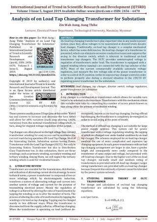
International Journal of Trend in Scientific Research and Development (IJTSRD) Volume 3 Issue 5, August 2019 Available Online: www.ijtsrd.com e-ISSN: 2456 – 6470 Study and Analysis of Insulator used in Substation Hnin Yu Lwin, U Hla Myo Htay Lecturer, Electrical Power Department, Technological University, Mandalay, Myanmar How to cite this paper: Hnin Yu Lwin | U Hla Myo Htay "Study and Analysis of Insulator used in Substation" Published in International Journal of Trend in Scientific Research and Development (ijtsrd), ISSN: 2456- 6470, Volume-3 | Issue-5, August 2019, pp.1160-1163, https://doi.org/10.31142/ijtsrd26578 Copyright © 2019 by author(s) and International Journal of Trend in Scientific Research and Development Journal. This is an Open Access article distributed under the terms of the Creative Commons Attribution License (CC BY (http://creativecommons.org/licenses/by /4.0) 1.INTRODUCTION Power system includes three parts such as generation, transmission and distribution. An electrical distribution system is all of that part of an electric power system between bulk power source or sources and the consumer's service switches. All types of electric utility customers such as residential, commercial, institutional and industrial are heavily dependent on the availability of electric power. Distribution substation is a combination of switching, controlling and voltage step down equipment arranged to reduce sub-transmission voltage to primary distribution voltage for residential, farm, commercial and industrial loads. Electricity distribution is the final stage in the delivery of electricity to end users. Electrical power systems utilize several voltage levels using power transformers to transfer voltages and connect parts of the power system with different voltage levels. Electric power distribution systems have many unique aspects and requirements. Distribution system can be divided into six parts, namely, sub-transmission circuits, distribution or primary feeders, distribution transformer, secondary circuits or secondary feeders and consumer’s service connections and meter. The distribution plant occupies and important place in any electric power system. Briefly, it function is to take electric from the bulk power source or sources and distribute or deliver it to the consumer’s. The effectiveness with a distribution system fulfills this function is measured in terms of voltage regulation, service continuity flexibility, efficiency and cost. These are completely depends upon sub-station design. The sub-transmission circuits extend from the bulk power sources to the various distribution sub-stations located in ABSTRACT The main purpose of this paper was that to compare design of post insulators and their performance of different post insulator the relative performance of different insulator materials used in substation as lightning arrester, current transformer and potential transformer. Insulators are used to protect from the dangerous effects of electricity flowing through conductors. This paper presents the role of post insulators are key components of most electrical substation equipment and their features and ability are changing due to the difference type of electrical power incoming line and pollution level of their rating. The peak voltage rating of each arrester at 132 kV is 118.6 kV, creepage distance is 2904 mm and maximum continuous operating voltage is 94.88 kV. The creepage distance of current transformer and potential transformer at 132 kV are 4065 mm. Therefore, in this paper, the effects of material changes, rating changes, pollution level changes of lightning arrester, current transformer and potential transformer in substation are described. Then, analysis and discussion of lightning arrester and instrument transformer are described in this paper. KEYWORDS: lightning arrester, current transformer, potential transformer, substation IJTSRD26574 4.0) the local area. They may be radial circuits connected to a bulk power source at only one end or load and ring circuits connected to one or more bulk power sources at both ends. The sub-transmission over head open wire conductions carried on poles, or some combination of them. The sub- transmission voltage is usually between 11 kV and 33 kV. The distribution substation must be required measuring and protected system to prevent equipment and circuits, hazards to the public and utility personal, and to maintain a high level of service by preventing power interruption. An electrical insulator is a material whose internal electric charges do not flow freely, and which therefore does not conduct an electric current, under the influence of an electric field. Insulators are used in electrical equipment to support and separate electrical conductors without allowing current through themselves. Insulators are the integral part of the power system. Among them polymeric insulators are essential for the better performance. There are many shapes and types of insulators used in power system transmission with different densities, tensile strengths and performing properties with the aim to withstand the worst conditions such as surge during lightning and switching operations which will voltage to spike. Reliability of the insulator is the most important property that must take into consideration whether it is a polymeric (composite) insulator or ceramic insulator. The good insulator should offer optimum electrical and mechanical strengths. 2.LITERATURE REVIEW The transition from transmission to distribution happens in a power substation, which has the following functions: distribution substation, @ IJTSRD | Unique Paper ID – IJTSRD26574 | Volume – 3 | Issue – 5 | July - August 2019 Page 1160
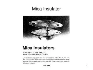
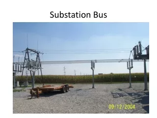
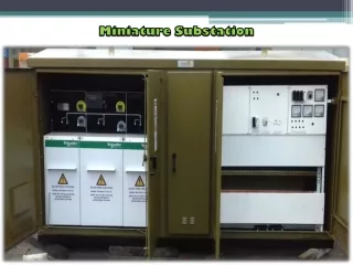
International Journal of Trend in Scientific Research and Development (IJTSRD) @ www.ijtsrd.com eISSN: 2456-6470 1.Circuit breakers and switches enable the substation to be disconnected from the transmission grid or for distribution lines to be disconnected. 2.Transformers step down transmission voltages, 35 kV or more, down to primary distribution voltages. These are medium voltage circuits, usually 600-35,000 V. 3.From the transformer, power goes to the bus-bar that can split the distribution power off in multiple directions. The bus distributes power to distribution lines, which fan out to customers. Urban distribution is mainly underground, sometimes in common utility ducts. Rural distribution is mostly above ground with utility poles, and suburban distribution is a mix. Closer to the customer, a distribution transformer steps the primary distribution power down to a low-voltage secondary circuit, usually 240 volts in the Myanmar for residential customers. The power comes to the customer via a service drop and an electricity meter. The main components of electrical distribution substation are: 1.Lightning Arrester 2.Capacitive Voltage Transformer 3.Disconnecting Switch With Earth 4.Gas Circuit Breaker 5.Disconnecting Switch 6.Current Transformer 7.Potential Transformer 8.Power Transformer 3.Sizing of Lightning Arrester Rating Choose of Surge Arresters are required by two paths as followings, 4.RESULT DATA OF LIGHTNING ARRESTER, CURRENT TRANSFORMER AND POTENTIAL TRANSFORMER Table 4.1 IEC Standard of Lightning Arrester NO. DESCRIPTION TYPE OF ARRESTER a Nominal system voltage (kV) b Highest system voltage (kV) c BIL of transformers (kVp) 1.Electrical characteristics and 2.Mechanical characteristics. Choose of electrical characteristics and mechanical characteristics are calculated as step by step as following figure. Performance of Choosing Arrester TECHNICAL PARAMETERS STATION CLASS HEAVY DUTY GAPLESS 400 220 420 245 1300 900 50 for 1 sec. 3 sec. 132 145 550 31.5 for 3 sec. 33 36 170 25 for 3 sec. 40 for d System fault level (kA) for 3 sec. Lightning Impulse withstand voltage for arrester housing (kVp) e 1425 1050 650 170 360 or as specified in the schedule 306 f Rated Voltage (kV) 198 120 42 g h Maxm. Continuous operating voltage (kVrms) Nominal Discharge Current (kAp) of 8/20 micro second wave 10//20 Line discharge class Minimum Energy Discharge capability (kJ/kV) at rated voltage Temporary over voltage withstand capability (kVrms) for 10.0 secs Insulation Housing withstand voltages i) Lightning Impulse (Dry) ii) Power frequency (wet) for 10 kA for 5 kA Minimum Creepage Distance (mm) Pressure Relief Class (Minimum) High Current Impulse withstand (4/10 micro second wave) kA (peak) 168 10 102 10 36 10 i 3 3 3 2 j 10 7.5 7.5 5 360 or as specified in the schedule k 198 120 42 l As per IEC 60099-4 m n 10500 A 6125 3625 900 o 100 100 100 100 @ IJTSRD | Unique Paper ID – IJTSRD26574 | Volume – 3 | Issue – 5 | July - August 2019 Page 1161
International Journal of Trend in Scientific Research and Development (IJTSRD) @ www.ijtsrd.com eISSN: 2456-6470 Maxm. Lightning Impulse (8/20 micro-second Wave) residual voltage (kVp) 5 kA 10 kA 800 850 517 550 320 340 112 120 p - - 750 - 455 - - 280 - 98 - - Maxm. switching surge (30/60 micro-second wave) protective level (kVp) 500 Amps 1000 Amps 2000 Amps q Maxm. Steep Impulse (1/20 MS impulse) residual voltage at 10 kA (kVp) Partial Discharge (pico-coulomb) when energized at 1.05 times its continuous operating voltage Rated Frequency (Hz) Minm. visible corona discharge voltage (kVrms) Min. Bending load (kgm) 1 min. p.f. withstand (kVrms) voltage (dry & wet) for arrestor housing Switching Impulse withstand voltage (250/2500 micro second) dry & wet for arrestor housing (kVp) Pressure relief Current i) High Current (kA rms) ii) Low Current (kA rms) r 1050 600 372 130 s Not exceeding 10 PC t u v 50 320 1000 - 1000 - 500 - 500 w 630 460 275 70 ± 1050 x - - - y 40 40 40 40 As per IEC Table 4.2 Analysis of Calculation Results for Post Insulator in LA System Voltage (kV) Nominal Creepage Distance (mm) 2904 Shed Number 132 33 726 Big 30, small 29 Big 9, small 8 Table 4.3 IEC Standard of Post Insulator (110 kV - 145 kV) for CT and PT 2814 2819 Rated Voltage (kV) 110 110 Nominal Creepage Distance (mm) Catalog No 2820 110 2821 110 2831 110 2650 3150 3150 3200 2016 Mechanic-al Load (min.) Withstand Voltage (kV) Power Frequency 16 50 Bending (kN) 16 6 10 20 Mechanical Load (min) Torsion (kN.m) 6.0 3.0 4.0 6.0 Lightning Impulse 450 450 450 450 Withstand Voltage (kV) Dry Wet 245 185 23 93 245 185 245 185 Power Frequency Shed Number Weight (kg) big 12 small 12 77 big 12 small 12 87 big 12 small 12 102 Table 4.4 IEC Standard of Post Insulator (20 kV - 35 kV) for CT and PT Catalog No Rated Voltage (kV) Nominal Creepage Distance (mm) Bending (kN) Torsion (kN.m) Lightning Impulse Dry Wet Shed Number Weight (kg) 2229 2200 2204 2206 2209 20 35 35 400 648 625 20 6 8 - 3.0 2.0 150 185 185 75 100 100 50 80 80 4 7 6 31 17 16 2213 35 1260 4 1.8 250 135 95 35 648 4 1.2 185 100 80 7 12 35 650 4 1.2 200 110 70 7 15 Mechanical Load (min) Withstand Voltage (kV) Power Frequ-ency big 5 small 4 27 5.CONCLUSIONS Electrical power distribution is the final stage in the delivery of electric power, it carries electricity from the transmission system to individual consumers. Insulators are the integral part of the power system. The insulators are subjected to the environmental stresses such as humidity, temperature and pollution. Therefore, it has dual functions as electrical and mechanical function in power system networks. Insulators are made from dielectric materials such as ceramic and non- ceramic insulating materials. Lightning arrester is made with non-ceramic insulating materials and current transformer and potential transformer are made with ceramic insulating material. @ IJTSRD | Unique Paper ID – IJTSRD26574 | Volume – 3 | Issue – 5 | July - August 2019 Page 1162
International Journal of Trend in Scientific Research and Development (IJTSRD) @ www.ijtsrd.com eISSN: 2456-6470 [3][14 Lig] Engineering (AESO), "Insulation coordination in the Alberta Interconnected Electric System", 2014. Lightning arrester and instrument transformers (CT and PT) are equipped at the incoming line and outgoing line of substation. Without equipping the instrument transformers, the substation may be damaged because of overcurrent and overvoltage. So, it is important to have right current and voltage rating of CT and PT for different lines. Numbers of shed, minimum creepage distance, dry arcing distance and diameter are differ according to its rating. In this paper, the efficiency and design of LA, the peak voltage rating of each arrester at 132 kV is 118.6 kV, creepage distance is 2904 mm and maximum continuous operating voltage is 94.88 kV. The creepage distance of current transformer and potential transformer at 132 kV are 4065 mm. 6.ACKNOWLEDGEMENTS The author deeply wants to express special appreciation and heart-left thanks to Dr. Yadana Aung, Professor and Head the Department of Electrical Power Engineering, Technological University (Mandalay) for her willingness to share her ideas and helpful suggestions on this paper writing. 7.REFERENCES [1][15 Tun] Tun Naing, "Potential Transformer and Surge Arrester", 2015. Ligong Gan, P-Eng Transmission [4][13 Koo] "High Voltage Engineering Practice and Theory", 2013. Koos Holtzhyousen and Dr WL Vosloo, [5][12 Ano] Insulators for Transmission Lines 69-500 kv", 2012. Anony mous, "3Fl Silicons long Rod [6][12 Ank] Insulator", 2012. AnkaRa Seramik, "Outdoor Solid Core Post [7][00 Zae] Engineering Fundamentals", 2nd [Ed] J.kuttel (2000). Zaengl, W.S and E-kuttel, "High Voltage [8][95 Fun] coordination in MV and HV", 1995. Funchiron, "Overvoltages and insulation [9][93 IEC] IEC, "Station Post Insulators", 1993. [10][92 IEC] Lines With Nominal Voltages Larger Thon 1000 V - Annexure C", 1992. IEC, "Composite Insulators for AC Overhead [11][88 Loo] Peter Peregriness, London, 1988. Looms, J.S.T, "Insulators for High Voltages", [12][86 IEC] Respect of Polluted Conditions", IEC Recommendations Publication 815, 1986. IEC, "Guide for the Selection of Insulators in [2][14 Ano] IEC, "Potential Post Insulators", 2014. @ IJTSRD | Unique Paper ID – IJTSRD26574 | Volume – 3 | Issue – 5 | July - August 2019 Page 1163