Download
1 / 4
40 likes | 41 Views
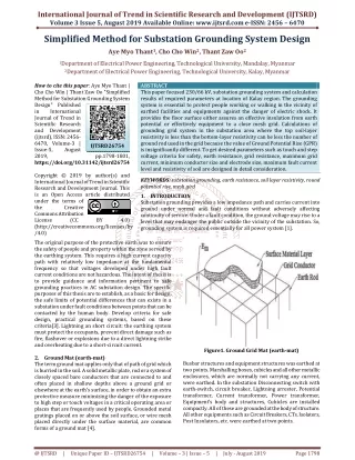
The design of earthing system for 230 kV substation is challenging task. A safety is one major concern in the operation and design of an electrical power system. This Paper is to provide information pertinent to safe earthing practice in substation design and to establish the safe limits of potential difference under normal and fault conditions. Substation earthing system design requires calculating of parameter such as touch and step voltage criteria for safety, grid resistance, maximum grid current, earth resistance, minimum conductor size and electrode size, maximum fault current level and soil resistivity. Soil resistivity is a major factor influencing substation grid design. In this paper, design of earthing grid for Square configuration to obtain the minimum cost and safety. Finally, simulation results were carried out using ETAP 12.6 software. This paper mentions the method proposed for substation earthing is in accordance with IEEE Std 80 2000. Khin Thuzar Soe | Thet Mon Aye | Aye Aye Mon "Design of Earthing System for 230 kV High Voltage Substation by ETAP 12.6 Software" Published in International Journal of Trend in Scientific Research and Development (ijtsrd), ISSN: 2456-6470, Volume-3 | Issue-5 , August 2019, URL: https://www.ijtsrd.com/papers/ijtsrd26747.pdf Paper URL: https://www.ijtsrd.com/engineering/electrical-engineering/26747/design-of-earthing-system-for-230-kv-high-voltage-substation-by-etap-126-software/khin-thuzar-soe<br>

E N D
International Journal of Trend in Scientific Research and Development (IJTSRD) Volume 3 Issue 5, August 2019 Available Online: www.ijtsrd.com e-ISSN: 2456 – 6470 Design of Earthing System for 230 kV High Voltage Substation by ETAP 12.6 Software Khin Thuzar Soe1, Thet Mon Aye2, Aye Aye Mon3 1Professor, 2Lecturer, 3Assistant Lecturer 1, 2, 3Department of Electrical Power Engineering, West Yangon Technological University, Yangon, Myanmar How to cite this paper: Khin Thuzar Soe | Thet Mon Aye | Aye Aye Mon "Design of Earthing System for 230 kV High Voltage Substation by ETAP 12.6 Software" Published in International Journal of Trend in Scientific Research and Development (ijtsrd), ISSN: 2456- 6470, Volume-3 | Issue-5, August 2019, https://doi.org/10.31142/ijtsrd26747 Copyright © 2019 by author(s) and International Journal of Trend in Scientific Research and Development Journal. This is an Open Access article distributed under the terms of the Creative Commons Attribution License (CC (http://creativecommons.org/licenses/by /4.0) The main function of earthing system in substation include; the first one is the ability carrying the electric currents into earth under normal and fault conditions without exceeding operating and exposed to the danger of electric shock [2]. The second is how this grounding system ensures that the person in the vicinity of grounded facilities is not exposed to the danger of electric shock. Designing grounding systems, building them and putting them in operation is a difficult task. The soil where the grounding system will be installed will generally be non-uniform. The flow of the earth system, cause voltage gradients ground level which cases different parts of the earth and the reference (ground round). (The ground potential rise (GPR) can be minimized by providing low resistance path to ground.) Due to the different in soil characteristics at each substation, ground grid design must carefully be done to gain acceptable safety as well as optimal investment. In this paper, ground grid design without rods and with rods was carried out [3]. The vertical rods considered but authorities only as total length conductor’s earth system optimization point are variable. A vertical rod is more effective electrode than a horizontal rod. Because, vertical ground rods discharge the grid current in the soil at sufficient depth. That, the ground potential rise (GPR) can be minimized by providing low resistance path to ground. Therefore, by using proper conductor and electrode size, earthing system may be able to overcome lightening effects. The grounding system of the substation should ABSTRACT The design of earthing system for 230 kV substation is challenging task. A safety is one major concern in the operation and design of an electrical power system. This Paper is to provide information pertinent to safe earthing practice in substation design and to establish the safe limits of potential difference under normal and fault conditions. Substation earthing system design requires calculating of parameter such as touch and step voltage criteria for safety, grid resistance, maximum grid current, earth resistance, minimum conductor size and electrode size, maximum fault current level and soil resistivity. Soil resistivity is a major factor influencing substation grid design. In this paper, design of earthing grid for Square configuration to obtain the minimum cost and safety. Finally, simulation results were carried out using ETAP 12.6 software. This paper mentions the method proposed for substation earthing is in accordance with IEEE Std 80-2000. KEYWORDS: Substation design, touch and step voltage, soil resistivity, ETAP 12.6 software, grounding grid I. INTRODUCTION Substation earthing system is very important for electric power system not only to provide the protection of people working in the vicinity of earthed facilities and equipment against danger of electric shock but also to maintain proper function of electrical system. IJTSRD26747 pp.1840-1843, BY 4.0) ensure the safe and reliable operation of power systems and guarantee a human being safety in the situation of grounding fault in the power system [2]. Study of unequally spaced grounding grids and optimum grounding grid design by using an evolutionary algorithm is considered. From the past, ground grid design without rods and with rods was carried out. Multiple driven electrodes are, everything being equal, more effective than equivalent ground grids made of horizontal conductors. This is true even when soil is uniform. However, when lower layer resistivity is high, the horizontal conductors are more effective because they reduce significantly the touch voltages Optimization design of substation grounding grid based on genetic algorithm is discussed [4]. II. DESIGN OBJECTIVES According to IEEE Std 80-2000 there are two main design goals to be achieved by any substation grounding system under normal as well as fault conditions. These goals are: To provide means to dissipate electric currents into the earth without exceeding any operating and equipment limits. To assure that a person in the vicinity of grounded facilities is not exposed to the danger of critical electric shock. @ IJTSRD | Unique Paper ID – IJTSRD26747 | Volume – 3 | Issue – 5 | July - August 2019 Page 1840
International Journal of Trend in Scientific Research and Development (IJTSRD) @ www.ijtsrd.com eISSN: 2456-6470 III. The design procedure block diagram in Figure 1 is the sort earthing studies of power networks and the algorithm can be expressed as follows: DESIGN METHODOLOGY 0.157 E (1000 6 C ρ ) (4) step,70 s s t s Input data ?,A 0.116 E (1000 1.5 C ρ ) (5) touch,50 s s t s Compute the conductor size 0.157 Compute Touch and Step Voltage Etouch,Estep 5 . 1 E (1000 C ρ ) (6) touch,70 s s t s Compute first design of Grid D,n,L,h Step 5: Preliminary design parameters like distance between equally spaced conductors, grid burial depth, total length of horizontal conductors and number of parallel conductors in one direction are determined. Step 6: The grid resistance is determined by equation 7. 1 20A L T Modify design D,n,LT Compute Grid Resistance Rg,Lc, Lr Compute fault Current IG,If Yes Compute IGRg<Etouch 1 1 1 R ρ (1 (7) g 20 h Compute mesh and step voltage Em,Es,Ki,Ks,Km,Kii,Kh A Step 7: Calculation of grid current The maximum grid current is determined by combining decrement factor and symmetrical grid current is given by equation 8 and 9. S 3I I ) I (3 S D I 0 f f Step 8: Calculation of the product of maximum grid current and grid resistance If it is less than the touch voltage, E R I Step 9: The mesh voltage and step voltage are determined by equation 11 and 12. K K I ρ E No Em < Etouch Es < Estep (8) g 0 f Detail design G (9) Figure1. Block Diagram for Earthing Network Design IV. Step 1: Start Step 2: Substation Data Data will be collected and important data from substation. Step 3: Calculation of conductor size Cross section used for wireless networks based on land- related equations, it is calculated and determined flow error (3I0) the maximum amount must be injected into the network during the probable future developments and continuing up to times short circuit current (tf), which includes the protection of backup is to be determined equations 1 and 2. V 3I 0 I A STEPS OF DESIGN (10) G g touch G m i (11) m L m ρ K K I S L i G E (12) s S Step 10: If the calculated mesh voltage is less than the touch voltage then proceeds for step 9, otherwise modify the design. Step 11: If the calculated step voltage is less than the step voltage then proceeds for detailed design, otherwise modify the design. Step 12: After calculating and determined all required grid parameters detailed design is prepared. V. SIMULATION AND TESTING RESULTS The design of a substation grounding system is very complex due to the number of involved phenomena. One of them comes from the fact that lightning influences the local resistivity of the soil given, when lightning occurs, non-linear phenomena appear in the soil. (1) 3R (R R R ) j(X X X ) f 1 2 0 1 2 0 (2) 2 4 mm TCAP 10 K T 0 m ln t α ρ K T c r r 0 a Step 4: Calculation of Tolerable step voltage and touch voltage are based on (3 _ 6). 0.116 ) ρ C 6 (1000 E (3) step,50 s s t s @ IJTSRD | Unique Paper ID – IJTSRD26747 | Volume – 3 | Issue – 5 | July - August 2019 Page 1841
International Journal of Trend in Scientific Research and Development (IJTSRD) @ www.ijtsrd.com eISSN: 2456-6470 Figure2. Square Grounding Grid without Rods Figure5. Screenshot of ETAP Software Figure3. Touch and step Voltage Value in ETAP Simulation Nevertheless, this is not the only difference regarding the low frequency case. Indeed, the high frequency response of both grounding grids and human body are not the same for fast transients and power frequency. In this section simulations are carried out in order to verify the results obtained through manual calculations. A software known as ETAP PowerStation is used for the simulations. The objectives of the program are: To provide a low cost computer program running on a personal computer. To provide an easy to use, but technically acceptable solution to the complex problem of grounding grid design. To design a safe, technically acceptable and economically viable grounding grid. Figure6. Screenshot of ETAP Software Figure7. Touch and Step Voltage Value in ETAP Simulation Table 1Design Parameters Without Rods 200ft 200ft 11 11 - - 2ft 551.6 923.9 5365.5 0.634 With Rods 200ft 200ft 11 11 44 30ft 2ft 461.6 360.2 4592.8 0.543 Parameter Lx Ly Grid length X-direction Y-direction Number of conductor Number of Rod Length of Rod Conductor depth Step Voltage Touch Voltage GPR Ground Resistance Rg Figure4. Square Grounding Grid with Rods @ IJTSRD | Unique Paper ID – IJTSRD26747 | Volume – 3 | Issue – 5 | July - August 2019 Page 1842
International Journal of Trend in Scientific Research and Development (IJTSRD) @ www.ijtsrd.com eISSN: 2456-6470 VI. In this grounding system for high voltage substation has been designed and the results are obtained by ETAP software. Construction of earthing grid is expressed in here. The step and touch voltages are dangerous for human body. Human body may get electric shocks from step and touch voltages. The final design shows that the resultant touch and steps voltages are within tolerable regions and no more enhancements are necessary. Other design modifications are useful in obtaining specific results. Rods are only effective in two layer soils. Reducing the mesh size is an admirable touch voltage reduction factor and when accompanied by a reduction in the overall ground resistant assist in reducing the step voltage. ACKNOWLEDGEMENT The author is grateful to her Rector, Dr. Kyi Soe, Rector of West Yangon Technological University. And also special thanks to Dr. Min Thu San, Head of Electrical Power Engineering Department, Dr. Thet Mon Aye, Lecturer, West Yangon Technological University, Daw Aye Aye Mon, Assistant Lecturer, West Yangon Technological University. REFERENCES [1]F. Dawalibi, D. Mukhedkar, “Optimum Design of Substation Grounding in a Two Layer Earth Structure, Part I: Analytical Study “, IEEE Trans, Power Apparatus and System, Vol. PAS-94, March, 1975, pp. 252 – 261. CONCLUSIONS Part II: Analytical Study”, IEEE Trans, Power Apparatus and System, Vol. PAS-94, March,1975, pp. 262 – 266. [3]F. Dawalibi, D. Mukhedkar, “Optimum Design of Substation Grounding in a Two Layer Earth Structure, Part III: Analytical Study “, IEEE Trans, Power Apparatus and System, Vol. PAS-94, April 1975, pp. 267 – 272. [4]J. L. He, Y. Q. Gao, R. Zeng, W. M. Sun, J. Zou, and Z. C. Guan,"Optimal Design Considering the Influence of Seasonal Frozen Soil Layer”, IEEE Trans. on Power Delivery, Vol. 20, Jan. 2005, pp. 107-115. of Grounding System [5]E. Bendito, A. Carmona, A. M. Encinas, and M. J. Jimenez, "The Extremal Charges Method in Grounding Grid Design” , IEEE Trans. on Power Delivery, Vol. 19, Jan. 2004, pp. 118-123. [6]IEEE Std. 80-2000, “IEEE Guide for Safety in AC Substation Grounding”, IEEE: Institute of Electrical and Electronic Engineers, Inc. New York, 2000. [7]L. Huang , X. Chen , and H. Yan ,“Study of Unequally Spaced Grounding Grids”, IEEE Transactions on Power Delivery, Vol. 10, No.2, April 1995, pp. 716- 722. [8]Ghoneim Sherif, Hirsch Holger, Elmorshedy Ahdab, and Amer Rabah, “Optimum Grounding Grid Design by Using an Evolutionary Algorithm”, IEEE Power Engineering Society General Meeting, 2007, 24-28 June 2007,pp1-7 [2]F. Dawalibi, D.Mukhedkar, “Optimum Design of Substation Grounding in a Two Layer Earth Structure, @ IJTSRD | Unique Paper ID – IJTSRD26747 | Volume – 3 | Issue – 5 | July - August 2019 Page 1843