Download
1 / 4
40 likes | 54 Views
This paper describes the design and analyzes the Pelton wheel for generating power of 400 Watt. A Pelton wheel is considered as an impulse turbine, a turbine that converts pressure head into velocity head. This thesis is to calculate the input power, output power, buckets and speed ratio, length of belt and efficiency of the turbine. The turbine with a jet diameter of 0.0254 m has been designed for the operational conditions of the Pelton wheel installed at the Mone Ta Wa Cave, Ayetharyar. The diameter of the runner is 0.254 m and the width of a bucket is 0.1143 m. The turbine has undergone efficiency testing and visual inspection during operation at a gross head of 20 m. The hydraulic efficiency is 96.35 and the output power is 400 Watt. Ma Myat Win Khaing | Ma Yi Yi Khin | Mg Than Zaw Oo "Design and Analysis of Pelton Wheel" Published in International Journal of Trend in Scientific Research and Development (ijtsrd), ISSN: 2456-6470, Volume-3 | Issue-5 , August 2019, URL: https://www.ijtsrd.com/papers/ijtsrd26477.pdf Paper URL: https://www.ijtsrd.com/engineering/mechanical-engineering/26477/design-and-analysis-of-pelton-wheel/ma-myat-win-khaing<br>

E N D
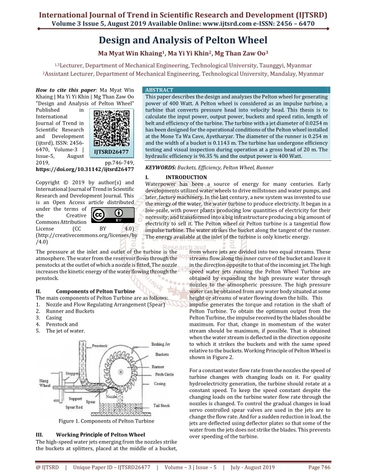
International Journal of Trend in Scientific Research and Development (IJTSRD) Volume 3 Issue 5, August 2019 Available Online: www.ijtsrd.com e-ISSN: 2456 – 6470 Design and Analysis of Pelton Wheel Ma Myat Win Khaing1, Ma Yi Yi Khin2, Mg Than Zaw Oo3 1,3Lecturer, Department of Mechanical Engineering, Technological University, Taunggyi, Myanmar 2Assistant Lecturer, Department of Mechanical Engineering, Technological University, Mandalay, Myanmar How to cite this paper: Ma Myat Win Khaing | Ma Yi Yi Khin | Mg Than Zaw Oo "Design and Analysis of Pelton Wheel" Published in International Journal of Trend in Scientific Research and Development (ijtsrd), ISSN: 2456- 6470, Volume-3 | Issue-5, August 2019, pp.746-749, https://doi.org/10.31142/ijtsrd26477 Copyright © 2019 by author(s) and International Journal of Trend in Scientific Research and Development Journal. This is an Open Access article distributed under the terms of the Creative Commons Attribution License (CC BY 4.0) (http://creativecommons.org/licenses/by /4.0) The pressure at the inlet and outlet of the turbine is the atmosphere. The water from the reservoir flows through the penstocks at the outlet of which a nozzle is fitted. The nozzle increases the kinetic energy of the water flowing through the penstock. II. Components of Pelton Turbine The main components of Pelton Turbine are as follows: 1.Nozzle and Flow Regulating Arrangement (Spear) 2.Runner and Buckets 3.Casing 4.Penstock and 5.The jet of water. ABSTRACT This paper describes the design and analyzes the Pelton wheel for generating power of 400 Watt. A Pelton wheel is considered as an impulse turbine, a turbine that converts pressure head into velocity head. This thesis is to calculate the input power, output power, buckets and speed ratio, length of belt and efficiency of the turbine. The turbine with a jet diameter of 0.0254 m has been designed for the operational conditions of the Pelton wheel installed at the Mone Ta Wa Cave, Ayetharyar. The diameter of the runner is 0.254 m and the width of a bucket is 0.1143 m. The turbine has undergone efficiency testing and visual inspection during operation at a gross head of 20 m. The hydraulic efficiency is 96.35 % and the output power is 400 Watt. KEYWORDS: Buckets, Efficiency, Pelton Wheel, Runner I. INTRODUCTION Waterpower has been a source of energy for many centuries. Early developments utilized water wheels to drive millstones and water pumps, and later, factory machinery. In the last century, a new system was invented to use the energy of the water, the water turbine to produce electricity. It began in a low-scale, with power plants producing low quantities of electricity for their necessity; and transformed into a big infrastructure producing a big amount of electricity to sell it. The Pelton wheel or Pelton turbine is a tangential flow impulse turbine. The water strikes the bucket along the tangent of the runner. The energy available at the inlet of the turbine is only kinetic energy. IJTSRD26477 from where jets are divided into two equal streams. These streams flow along the inner curve of the bucket and leave it in the direction opposite to that of the incoming jet. The high speed water jets running the Pelton Wheel Turbine are obtained by expanding the high pressure water through nozzles to the atmospheric pressure. The high pressure water can be obtained from any water body situated at some height or streams of water flowing down the hills. This impulse generates the torque and rotation in the shaft of Pelton Turbine. To obtain the optimum output from the Pelton Turbine, the impulse received by the blades should be maximum. For that, change in momentum of the water stream should be maximum, if possible. That is obtained when the water stream is deflected in the direction opposite to which it strikes the buckets and with the same speed relative to the buckets. Working Principle of Pelton Wheel is shown in Figure 2. For a constant water flow rate from the nozzles the speed of turbine changes with changing loads on it. For quality hydroelectricity generation, the turbine should rotate at a constant speed. To keep the speed constant despite the changing loads on the turbine water flow rate through the nozzles is changed. To control the gradual changes in load servo controlled spear valves are used in the jets are to change the flow rate. And for a sudden reduction in load, the jets are deflected using deflector plates so that some of the water from the jets does not strike the blades. This prevents over speeding of the turbine. Figure 1. Components of Pelton Turbine III. The high-speed water jets emerging from the nozzles strike the buckets at splitters, placed at the middle of a bucket, Working Principle of Pelton Wheel @ IJTSRD | Unique Paper ID – IJTSRD26477 | Volume – 3 | Issue – 5 | July - August 2019 Page 746
International Journal of Trend in Scientific Research and Development (IJTSRD) @ www.ijtsrd.com eISSN: 2456-6470 The actual power developed by the Pelton wheel is P η (W.P) η S.P = = Where, efficiency Overall o η Inlet and Outlet Velocity Triangles of the Bucket 5 o o t = V = V 1 1u 1rV 2β θ 180 Figure2. Working Principle of Pelton Wheel = − o β2 θ IV. The velocity of Jet (V), The theoretical velocity of the jet is given by 2gH V theo = Where, H = Net head. The actual velocity of the jet is given by 2gH V act Where, Cv = The coefficient of velocity. The value of Cv from 0.98 to 0.99. Velocity of Wheel (u), The velocity of wheel is given by 2gH φ u = Where, ratio Speed φ = The value of the speed ratio varies from 0.43 to 0.47.Its average value is 0.45. Theoretical Power (Pt) The power available from water can be estimated from the equation ρgQH tP Where, = g = Gravity acceleration constant (9.81m/s2) Q= Discharge (m3/s) H= Net head (m) The theoretical power is also called the water power (W.P). Power supplied to the runner (P1) is given by P1=Pt –Power loss in the nozzle P1=Pt=W.P If the losses in the nozzle are neglected. Design Theory 2rV 1 fV 2V 2β 2uV Figure3. Velocity Triangles for the Jet Striking the Bucket = V C 2 The blade is divided into two parts to avoid side thrust or axial thrust V1 & V2 =Velocity of the jet at inlet and outlet U1 & U2 =Tangential Velocity of Impeller at inlet and outlet Vw1 &Vw2 =Whirl velocity at inlet and outlet Vr1 &Vr2 =Relative velocity at inlet and outlet Vf1&Vf2 =Flow velocity at inlet and outlet θ =Angle made by the relative velocity with inlet with the direction of motion of the curve Jet Ratio (m), The ratio of the pitch diameter (D) to the jet diameter (d) is known as the jet ratio. D (m) Ratio Jet = 3 6 d Size of Buckets, The following proportions of the bucket are usually adopted. = 4 3 ρ density The of water (kg/m ) Figure4. Dimensions of Bucket The radial length of the bucket, L =2 to 3d Axial width of the bucket, B Depth of bucket, D 7 8 9 =3 to 5d =0.8 to 1.2d @ IJTSRD | Unique Paper ID – IJTSRD26477 | Volume – 3 | Issue – 5 | July - August 2019 Page 747
International Journal of Trend in Scientific Research and Development (IJTSRD) @ www.ijtsrd.com eISSN: 2456-6470 Where d is the diameter of the jet. The number of bucket is given by; D 15 z + = 10 2d The hydraulic efficiency of the turbine equation is from the velocity diagram; [ 2 1 Where; V V V1 =Velocity of jet u = Tangential velocity of the vane Mechanical Efficiency, The mechanical efficiency is defined as the ratio of the power obtained at the shaft power developed by the runner. η η = Overall Efficiency, The overall efficiency of the turbine is the ratio of the shaft power to the power supplied to the turbine. S.P 0 η η η × = Shaft Diameter, A shaft is a rotating machine element, usually circular in cross-section, which is used to transmit power from one part to another, or from a machine which produces power to a machine which absorbs power. 60 Power T × × 16T s =15+0.5 m ] Figure5. B Selection V Belt + × 2 V V u Angle of Wrap or Angle of Contact for an Open Belt ω ω 1 2 = 11 η h V α α D 2 D = Velocity of whirl at the inlet 1 2θ w θ α 1 1 = Velocity of whirl at the outlet w 2 C Figure6. Open Belts with Pulley D − D 2 1 = 16 sin α 2C o 12 m − η D D − 1 2 1 o o 1 h = − = − 17 180 2α 180 2sin θ 1 2C − D D − 2 1 o o = + = + 18 180 2α 180 2sin θ 2 2C 2 = η − (D D ) π tP 2 1 = + + + 19 L 2C (D D ) 2 1 2 4C 13 o m h Where, D1 = Diameter of smaller pulley (m) D2 = Diameter of larger pulley (m) wrap of Angle 1 wrap of Angle 2 C =Center distance between two pulley (m) L =Length of belt (m) Power Transmitted by the Belt, ) 2 1 Where, T1=Belt tension in tight side, N T2=Belt tension in slack side, N V =Belt velocity, m/s friction of t Coefficien µ = belt, V of ratio Tension − T log( 2.3 = θ = of smaller pulley degree ( ) = of larger pulley degree ( ) θ × = 14 2 N π = − × 20 power/belt (T T v (Watt) D = 3 15 πS s Where, T=Torque (N-m) Ss=Allowable shear stress (N/m2) ASME Code states for commercial steel shafting without ), MN/m (55 psi 8000 s 2 MN/m psi(40 6000 s between pulley and belt 2 S = keyway for shaft 1 21 ) µθcosecβ S = ), with keyway for shaft T 2 Selection of Belt Type, Use, B 130 - B Selection V Belt Material, Rubber cushion. B Selection V Belt is shown in Figure 5. Where, T 1 = Tension in tight side of the belt and slack side T θ = 2 Angle of contact @ IJTSRD | Unique Paper ID – IJTSRD26477 | Volume – 3 | Issue – 5 | July - August 2019 Page 748
International Journal of Trend in Scientific Research and Development (IJTSRD) @ www.ijtsrd.com eISSN: 2456-6470 V. Calculation Data, Net head, Calculation Result 3 = Water Specific Coefficient of velocity, cv =0.98 Diameter of wheel, Diameter of jet, density, gravity, ρ g 1000 9.81 = kg/m m/s 2 H = 20 m = N =170 rpm 3 Discharge, Turbine speed, Q 0.00229 m /s D =0.254 m dj =0.0254 m Table I. The Calculated Result Table for Pelton Wheel Parameters Symbol Calculating Result Existing Result Error % Net Hea net H 20 tP 449.29 Actual Power P 404.36 No. 1 Unit m 20 - 2 3 Theoretical Power - - Watt Watt 400 1.092 4 Theoretical velocity of jet 19.81 - - m/s V theo V u D dj L B D Z h η η 5 6 7 8 9 10 11 12 13 Actual velocity of jet Velocity of wheel Diameter of wheel Diameter of jet Radial Length of bucket Axial width of bucket Depth of bucket Number of buckets Hydraulic Efficiency Mechanical Efficiency Overall Efficiency Shaft diameter Length of belt 19.412 8.914 0.254 0.025 0.0635 0.114 0.03 20 96.35 - - - m/s m/s m m m m m buckets % 1 0.1905 0.0254 - 0.0762 0.0190 20 - 33.333 - - 50 57.480 - - 14 93.41 - - % m o η ds Lb 15 16 17 90 0.014 2.326 - - % m m 0.025 - -44 - VI. The hydraulic turbine is one of the most important parts to generate electricity. In this thesis, different types of hydraulic turbines are briefly discussed and three types of impulse turbine are described. Pelton wheel is generally used as a powerful mechanical device. Head is the most important in the Pelton turbine. In this thesis, the gross head and diameter of the jet are 20 m and 0.0254 m. The wheel with a pitch or mean diameter of 0.254 m has been designed for the operational conditions of the radial length of buckets is 0.0635 m and depth of buckets is 0.03 m. The velocity of the jet is 19.412 meter per second and velocity on buckets is 8.914 meter per second. As Pelton wheel designed is simple and easy to construct, this wheel can be manufactured by any simple workshop having facilities to weld, drill and cutting machine. The Pelton wheel can be used for more than 15 m head of water. It can be built with local material and the cost is low. Then, Pelton wheels have high speed and their speed can be raised by means of gearbox or pulley. Discussions and Conclusion VII. [1]file:///c:Users/Documents/Hydraulic Machines Fluid Machinery-R. K. singal, Mridual Singal-Google Books.htm REFERENCES [2]FLUID MECHANICS, HYDRAULICS AND HYDRAULIC MACHINES (Dr. K.R.ARORA) [3]https: //en.wikipedia.org/wiki/Pelton-wheel [4]https://www.scribd.com/doc/305864506/Pelton- Turbine-Thesis-Report-AUST [5]https://en.wikipedia.org/wiki/Belt_(mechanical) [6]http://www.pureenergy.com.ph/repowerenergy/ [7]http://pakwindturbine.blogspot.de/2014/03/advanta ges-and-disadvantages-of-pelton.ht [8]THEORY OF MACHINES, R. S. KHURMI, J. K. GUPTA (ME 32015) @ IJTSRD | Unique Paper ID – IJTSRD26477 | Volume – 3 | Issue – 5 | July - August 2019 Page 749