Download
1 / 6
60 likes | 77 Views
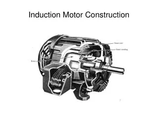
This project is designed to control the speed of a single phase induction motor by using cycloconvertor technique by traics. Induction motors in particular are very robust and therefore used in many domestic appliances such as washing machines, vacuum cleaners, water pumps, and used in industries as well. A.C. motors have the great advantages of being relatively inexpensive and very reliable. The induction motor is known as a constant speed machine, the difficulty of varying its speed by a cost effective device is one of its main disadvantages. The speed of the motor can be varied in two ways, one is by changing the number of poles and the second method is by changing the frequency. The speed control through the first method is uneconomical and the number of poles can't be varied under running conditions and the size of the machine also becomes bulky. These problems can be overcome by the second method. In this method, the frequency can be varied under running conditions also and there is no change in the size of the motor. In this method, the frequency changing device is cycloconverter. A cycloconverter is a power electronic device used to convert constant voltage constant frequency AC power to adjustable voltage adjustable frequency AC power without a DC link. In among all the methods this method is simple, reliable and economical. A pair of slide switches is provided to select the desired speed range f, f 2, f 3, f 4 and f 5 of operation of the induction motor. These switches are interfaced to the microcontroller. The microcontroller used for this project is from PIC18 family PIC18F4550 . The status of the switches enables the microcontroller to deliver the pulses to trigger the traic in a dual bridge. Thus, the speed of the induction motor can be achieved in five steps i.e. f, f 2, f 3, f 4 and f 5 . Aye Aye Nyein "Analysis of Cycloconverter Fed Induction Motor Drive" Published in International Journal of Trend in Scientific Research and Development (ijtsrd), ISSN: 2456-6470, Volume-3 | Issue-1 , December 2018, URL: https://www.ijtsrd.com/papers/ijtsrd19041.pdf Paper URL: http://www.ijtsrd.com/engineering/electrical-engineering/19041/analysis-of-cycloconverter-fed-induction-motor-drive/aye-aye-nyein<br>

E N D
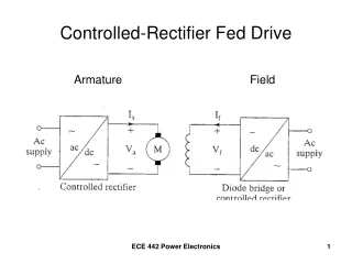
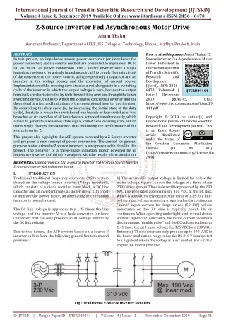
International Journal of Trend in International Open Access Journal International Open Access Journal | www.ijtsrd.com International Journal of Trend in Scientific Research and Development (IJTSRD) Research and Development (IJTSRD) www.ijtsrd.com ISSN No: 2456 ISSN No: 2456 - 6470 | Volume - 3 | Issue – 1 | Nov 1 | Nov – Dec 2018 Analysis of Cycloconverter Fed f Cycloconverter Fed Induction Motor Drive Induction Motor Drive Aye Aye Nyein Department Technological Univer Technological University, Thanlyin, Myanmar Department of Electrical Power Engineering, ABSTRACT This project is designed to control the speed of a single phase induction motor by using cycloconvertor technique by traics. Induction motors in particular are very robust and therefore used in many domestic appliances such as washing machines, vacuum cleaners, water pumps, and used in industries as well. A.C. motors have the great advantages of being relatively inexpensive and very reliable. The induction motor is known as a constant machine, the difficulty of varying its speed by a cost effective device is one of its main disadvantages. The speed of the motor can be varied in two ways, one is by changing the number of poles and the second method is by changing the frequency. The speed control through the first method is uneconomical and the number of poles can’t be varied under running conditions and the size of the machine also becomes bulky. These problems can be overcome by the second method. In this method, the frequency can be varied under running conditions also and there is no change in the size of the motor. In this method, the frequency changing device is cycloconverter. A cycloconverter is a power electronic device used to convert constant voltage constant frequency AC power to adjustable voltage adjustable frequency AC power without a DC link. In among all the methods this method is simple, reliable and economical. A pair of slide switches is provided to select the desired speed range (f, f/2, f/3, f/4 and f/5) of operation of the induction motor. These switches are interfaced to the microcontroller. The microcontroller used for this project is from PIC18 family (PIC18F4550). The status of the switches enables the microcontroller to deliver the pulses to trigger the traic in a dual bridge. Thus, the speed of the induction motor can be achieved in five steps i.e. (f, f/2, f/3, f/4 and f/5). KEY WORDS: Cycloconverter, Induction Motor, Microcontroller, Supply Frequency 1.INTRODUCTION With the increasing motor loads for industrial applications the concept of energy saving has become vital. About 70% of the electrical loads are motor loads. Hence, the requirement of energy savings in electric drives is achieved through power electronic converters. Variable frequency drives are mostly used for controlling either the torque or the speed of the AC motor. Applications such as pumps, centrifugal use the technique of variable frequency to achieve variable speed and variable torque. Variable frequency in AC drives can be achieved by inverter fed or cycloconverter fed drives. The advantage of cycloconverter over inverter fed drive is its single stage conversion. 2.CYCLOCONVERTER Cycloconverters are the direct type converters used in high power applications for driving induction and synchronous motors. Cycloconverters are usually phase-controlled device. Cycloconverter is a device which converts the AC power at one frequency input to a AC power at different frequency output. frequency output. This project is designed to control the speed of a single phase induction motor by using cycloconvertor technique by traics. Induction motors in particular are very robust and therefore used in many domestic appliances such as washing machines, vacuum ners, water pumps, and used in industries as well. A.C. motors have the great advantages of being relatively inexpensive and very reliable. The induction motor is known as a constant-speed machine, the difficulty of varying its speed by a cost vice is one of its main disadvantages. The speed of the motor can be varied in two ways, one is by changing the number of poles and the second method is by changing the frequency. The speed control through the first method is uneconomical and poles can’t be varied under running conditions and the size of the machine also becomes bulky. These problems can be overcome by the second method. In this method, the frequency can be varied under running conditions also and there is no e of the motor. In this method, the frequency changing device is cycloconverter. A cycloconverter is a power electronic device used to convert constant voltage constant frequency AC power to adjustable voltage adjustable frequency AC k. In among all the methods this method is simple, reliable and economical. A pair of slide switches is provided to select the desired speed range (f, f/2, f/3, f/4 and f/5) of operation of the induction motor. These switches are interfaced to the troller. The microcontroller used for this project is from PIC18 family (PIC18F4550). The status of the switches enables the microcontroller to deliver the pulses to trigger the traic in a dual bridge. Thus, the speed of the induction motor can be in five steps i.e. (f, f/2, f/3, f/4 and f/5). With the increasing motor loads for industrial applications the concept of energy saving has become vital. About 70% of the electrical loads are motor Hence, the requirement of energy savings in electric drives is achieved through power electronic Variable frequency drives are mostly used for controlling either the torque or the speed of the AC motor. Applications such as pumps, centrifugal fan use the technique of variable frequency to achieve variable speed and variable torque. Variable frequency in AC drives can be achieved by inverter fed or cycloconverter fed drives. The advantage of over inverter fed drive is its single Cycloconverters are the direct type converters used in power applications for driving induction and motors. Cycloconverters are usually device. Cycloconverter is a device power at one frequency input Figure.1 Cycloconverter Cycloconverter ycloconverter is a type of power controller in which an alternating voltage at supply frequency is converted directly to an alternating voltage at load frequency without any intermediate DC stage. The cycloconverter also allows power to flow freely in A cycloconverter is a type of power which an alternating voltage at supply converted directly to an alternating voltage at frequency without any intermediate DC stage. The cycloconverter also allows power to flow freely in either direction [3]. Cycloconverter, Induction Motor, @ IJTSRD | Available Online @ www.ijtsrd.com www.ijtsrd.com | Volume – 3 | Issue – 1 | Nov-Dec 2018 Dec 2018 Page: 569
International Journal of Trend in Scientific Research and Development (IJTSRD) ISSN: 2456 International Journal of Trend in Scientific Research and Development (IJTSRD) ISSN: 2456 International Journal of Trend in Scientific Research and Development (IJTSRD) ISSN: 2456-6470 There are three types of cycloconverter: 1.Single Phase to Single phase cycloconverter. 2.Three Phase to Three Phase cycloconverter. 3.Single Phase to Three Phase cycloconverter types of cycloconverter: 1.Single ycloconverter. 2.Three Phase ter. 3.Single Phase to induction. In this case, this would be step down the induction. In this case, this would be step down the 220 VAC into 15 VAC. Bridge Rectifier: This cycloconverter electronics components which are operated on DC voltages therefore the AC voltages are converted into DC through bridge rectifier, which consists of four diodes and connected at the output of t Voltage Regulator: In cycloconverter drive, the voltage regulator is used for regulator the DC voltages which comes from the bridge rectifier. It regulates the 15 VDC into 5 VDC and for this purposes, the LM7805 voltage re are used. Microcontroller PIC 18F4550 cycloconverter drive the PIC 18F45 are used for the intelligent control of this drive. This microcontroller controls the firing angle of the voltages for controlling the speed of motor in steps. It is powered up with 5 VDC and interfaced with the optocouplers. It is 40 pins microcontroller and programmed in C language with the help of mikro/C software. Zero-Crossing Detector: The micro programmed i.e. C program to give output to isolation with zero cross detection circuit. It compares two signals in order to get zero crossing whenever the zero crossing occurs it gives an output. Mode Selection: In this drive the selection mode is basically the switch, which is used for the selection of frequency and this drive is designed for frequency steps. Motor: In this traic, controlled cyclo the single-phase AC induction through this drive which is basically the inductive load. The working principle of cycloconverter drive for controlling the speed of induction motor are as follows. This traic controlled cycloconverter drive works the principle of variable frequency drive, when the frequency is changed then the speed is also changed. In this paper, first the single-phase induction motor is driven at fundamental frequency which is 50 Hz, then at f/2 Hz and then f/3 Hz at f/2 Hz and then f/3 Hz, f/4 Hz and f/5 Hz cycloconverter drive consists of electronics components which are operated on DC voltages therefore the AC voltages are converted into DC through bridge rectifier, which consists of four diodes and connected at the output of transformer. Regulator: drive, the voltage regulator is used for regulator the DC voltages which comes from the bridge rectifier. It regulates the 15 VDC into 5 VDC and for this purposes, the LM7805 voltage regulator Voltage In this this traic controlled Figure.2 Single-Phase to Single-Phase Cycloconverter 3.PROPOSED TOPOLOGY Cycloconverter is a power electronic circuit that converts fixed voltage fixed frequency input AC voltage to variable voltage variable frequency output AC. The output frequency may be greater than input frequency (step up cycloconverter) or the output frequency may be less than the input frequency (step down cycloconverter). Phase Cycloconverter 50: In this traic controlled drive the PIC 18F4550 microcontroller are used for the intelligent control of this drive. This microcontroller controls the firing angle of the traic voltages for controlling the speed of motor in five steps. It is powered up with 5 VDC and interfaced with the optocouplers. It is 40 pins microcontroller and programmed in C language with the help of is a power electronic circuit that converts fixed voltage fixed frequency input AC voltage to variable voltage variable frequency output AC. The output frequency may be greater than input ) or the output ess than the input frequency (step Crossing Detector: The microcontroller has been programmed i.e. C program to give output to optical detection circuit. It compares signals in order to get zero crossing whenever the zero crossing occurs it gives an Mode Selection: In this drive the selection mode is basically the switch, which is used for the selection of frequency and this drive is designed for five Figure.3 Block Diagram of Proposed Cycloconverter Controlled Induction Motor Drive Controlled Induction Motor Drive Block Diagram of Proposed Cycloconverter The block diagram for the traic cycloconverter drive for controlling the speed of induction motor is shown in Fig. 3. This traic controlled cycloconverter drive has following components: transformer, rectifier, filter, voltage regulator, zero-crossing detector, tap changer controller, triac control circuit, cycloconverter, microcontroller, frequency display and single phase induction motor. Transformer: In this traic controlled cycloconverter drive, the transformer is used for step down the AC voltages and works on the principle of mutual voltages and works on the principle of mutual his traic, controlled cycloconverter drive, phase AC induction motor is controlled through this drive which is basically the inductive traic controlled cycloconverter drive for controlling the speed of The working principle of the traic controlled converter drive for controlling the speed of induction motor are as follows. This traic controlled cycloconverter drive has following components: transformer, rectifier, filter, crossing detector, tap changer controller, triac control circuit, cycloconverter, converter drive works on lay and single phase the principle of variable frequency drive, when the frequency is changed then the speed is also changed. phase induction motor is cycloconverter driven at fundamental frequency which is 50 Hz, then drive, the transformer is used for step down the AC @ IJTSRD | Available Online @ www.ijtsrd.com www.ijtsrd.com | Volume – 3 | Issue – 1 | Nov-Dec 2018 Dec 2018 Page: 570
International Journal of Trend in Scientific Research and Development (IJTSRD) ISSN: 2456 International Journal of Trend in Scientific Research and Development (IJTSRD) ISSN: 2456 International Journal of Trend in Scientific Research and Development (IJTSRD) ISSN: 2456-6470 respectively. At fundamental frequency, the motor runs at its full speed which could be checked by the tachometer, then it would be drive at f/2 then the motor runs at half speed and then motor is drive at f/3, at this frequency the motor speed coul This drive consists of switch which is for frequency selection mode. The microcontroller basically increase or decrease delay time of the trigging signal, which is inversely proportional to the speed of the single The delay time is set in microcontroller through programming. 4.PERFORMANCE SIMULATION RESULTS Accurate simulation of electrical and electronic control systems would save many hours of prototype development. In this paper the Proteus Virtual System Modeller (VSM) software from Labcenter Electronics Ltd is used to provide such simulation environment. The Zero Crossing Detector Circuit for cycloconverter fed induction motor drive in Proteus Simulation is as shown in Fig. 4. . At fundamental frequency, the motor runs at its full speed which could be checked by the tachometer, then it would be drive at f/2 then the motor runs at half speed and then motor is drive at f/3, at this frequency the motor speed could be quarter. This drive consists of switch which is for frequency The microcontroller basically increase or decrease delay time of the trigging signal, which is inversely proportional to the speed of the single-phase motor. is set in microcontroller through PERFORMANCE ANALYSIS ANALYSIS AND AND Figure.6 Simulation Test Result Simulation Test Result for Frequency (f) electrical and electronic systems would save many hours of prototype development. In this paper the Proteus Virtual System (VSM) software from Labcenter Electronics Ltd is used to provide such simulation environment. In Fig. 7, the program flowchart for frequency (f described and simulation test result simulation test result is shown in Fig. 8. flowchart for frequency (f/2) is for cycloconverter fed induction motor drive in Proteus Simulation is as Figure.4 Zero Crossing Detector Circuit In Fig. 5, the program flowchart for frequency (f) described and simulation test result is shown in Fig. program flowchart for frequency (f) is is shown in Fig. 6. Figure.7 Program Flowchart Program Flowchart for Frequency (f/2) Figure.5 Program Flowchart for Frequency (f) Frequency (f) @ IJTSRD | Available Online @ www.ijtsrd.com www.ijtsrd.com | Volume – 3 | Issue – 1 | Nov-Dec 2018 Dec 2018 Page: 571
International Journal of Trend in Scientific Research and Development (IJTSRD) ISSN: 2456 International Journal of Trend in Scientific Research and Development (IJTSRD) ISSN: 2456 International Journal of Trend in Scientific Research and Development (IJTSRD) ISSN: 2456-6470 In Fig. 11, the program flowchart for frequency (f is described and simulation test result Fig.12 program flowchart for frequency (f/4) simulation test result is shown in 12. Figure.8 Simulation Test Result for Frequency (f Frequency (f/2) In Fig. 9, the program flowchart for frequency (f described and simulation test result is shown in Fig. 10. program flowchart for frequency (f/3) is is shown in Fig. Figure.9 Program Flowchart for Frequency (f/ Frequency (f/3) Figure.11 Program Flowchart Program Flowchart for Frequency (f/4) Figure.10 Simulation Test Result for Frequency (f Frequency (f/3) Figure.12 Simulation Test Result Simulation Test Result for Frequency (f/4) @ IJTSRD | Available Online @ www.ijtsrd.com www.ijtsrd.com | Volume – 3 | Issue – 1 | Nov-Dec 2018 Dec 2018 Page: 572
International Journal of Trend in Scientific Research and Development (IJTSRD) ISSN: 2456 International Journal of Trend in Scientific Research and Development (IJTSRD) ISSN: 2456 International Journal of Trend in Scientific Research and Development (IJTSRD) ISSN: 2456-6470 In Fig. 13, the program flowchart for frequency (f is described and simulation test result is shown in Fig. 14. program flowchart for frequency (f/5) In Fig. 15 and Fig. 16 shows the Proteus test results. shows the Proteus test results. is shown in Fig. Figure.15 Proteus Test Proteus Test 1 Figure.16 Proteus Test 2 Proteus Test 2 CONCLUSION A cycloconverter is a device use to convert a constant voltage constant frequency AC power to variable voltage variable frequency without any intermediate DC link. This paper presented a speed control of single phase induction motor by using cycloconverter. There are several techniques use conversion but order to have maximum converter utilization, special cycloconverter techniques have to be used. Cycloconverter circuit have for speed control of induction motor frequency. Single phase c change the speed of induction motor with the help of microcontroller, different desired frequency is obtained to equalize the desired speed. This different frequency of cycloconverter is obtain of adjustable speed to f, f/2, f/3, f/4 and f ACKNOWLEDGMENTS The author would like to express her profound gratitude to Dr. Theingi, Rector, Technological University (Thanlyin), for her encouragement and managements and the author wou thanks to thesis supervisor, Dr. Professor of Electrical Power motivation and encouragement to complete this research in time. After all, the author would like to express her thanks to all her te for their supports and encouragements. for their supports and encouragements. A cycloconverter is a device use to convert a constant constant frequency AC power to variable frequency without any intermediate presented a speed control of single phase induction motor by using single phase cycloconverter. There are several techniques used for conversion but order to have maximum converter special cycloconverter techniques have to converter circuit have been designed for speed control of induction motor for adjustable Figure.13 Program Flowchart for Frequency (f/ Frequency (f/5) cycloconverter used to change the speed of induction motor with the help of microcontroller, different desired frequency is obtained to equalize the desired speed. This different frequency of cycloconverter is obtaind in the manner , f/3, f/4 and f/5. The author would like to express her profound gratitude to Dr. Theingi, Rector, Technological University (Thanlyin), for her encouragement and managements and the author would like to express her thanks to thesis supervisor, Dr. Su Hlaing Myint, ectrical Power Engineering, for her motivation and encouragement to complete this research in time. After all, the author would like to express her thanks to all her teachers and her parents, Figure.14 Simulation Test Result for Frequency (f Frequency (f/5) @ IJTSRD | Available Online @ www.ijtsrd.com www.ijtsrd.com | Volume – 3 | Issue – 1 | Nov-Dec 2018 Dec 2018 Page: 573
International Journal of Trend in Scientific Research and Development (IJTSRD) ISSN: 2456 International Journal of Trend in Scientific Research and Development (IJTSRD) ISSN: 2456 International Journal of Trend in Scientific Research and Development (IJTSRD) ISSN: 2456-6470 REFERENCES 1.https://www.elprocus.com/cycloconverters applications/ 2.https://ieeexplore.ieee.org/document/5533596 3.A Survey on Single Phase to Three Phase Cyclo Converter Fed Induction Motor; IJSRD Issue 10, 2015 ISSN 4.Survey on Thyristor Using Cyclo (IRJET) e-ISSN:2395 Issue:04|APRIL-2016p- 0072©2016,IRJET ISO 9001:2008 Certified Journal 5.Speed Control of Induction Motor using Cycloconverter; International Engineering Trends and Technology Volume4 Issue4-April 2013. 6.A Review on Speed Control Phase Induction Motor; International Journal of Computer Technology Engineering (IJCTEE) Volume 2012. 0072©2016,IRJET ISO 9001:2008 Certified https://www.elprocus.com/cycloconverters-types- Speed Control of Induction Motor using International Engineering Trends and Technology (IJETT) - April 2013. https://ieeexplore.ieee.org/document/5533596 Journal Journal of of A Survey on Single Phase to Three Phase Cyclo- ; IJSRD - Vol. 3, A Review on Speed Control Techniques of Single Induction Motor; International Journal of Technology Engineering (IJCTEE) Volume 2, Issue 5, October Survey on Thyristor Using Cyclo-converter and and Electronics Electronics 005; Volume:03 ISSN:2395- @ IJTSRD | Available Online @ www.ijtsrd.com www.ijtsrd.com | Volume – 3 | Issue – 1 | Nov-Dec 2018 Dec 2018 Page: 574