Download
1 / 4
40 likes | 64 Views
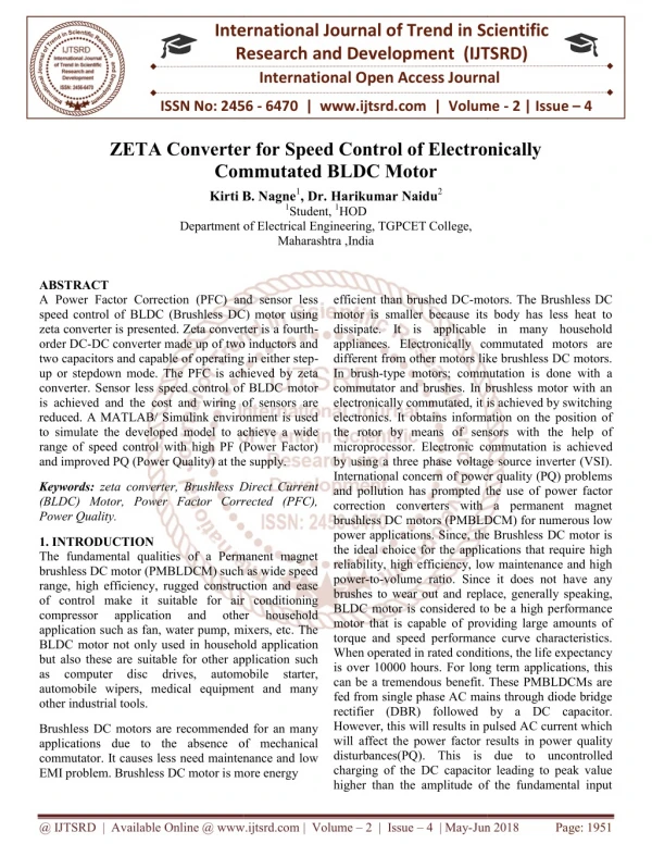
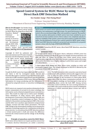
Nowadays, Brushless DC motors are in high demand due to its high efficiency and other significant features. As there is no use of brushes, this type of motor is having many advantages like high torque to inertia ratio, high speed, and power density and low cost compared to conventional brushed motors. This paper determines speed torque characteristics of brushless dc motor with different load variation by using the proposed method and the developed controller. The variation in motor speed torque characteristics for half load, full load, and overloading condition is analyzed. This research has been conducted to analyze the model and compared with the simulation results which are very useful in studying the performance of motor system. The simulation is carried out in MATLAB Simulink environment. Ishita Gupta | Akash Varshney "Speed-Torque Characteristics of BLDC Motor with Load Variations" Published in International Journal of Trend in Scientific Research and Development (ijtsrd), ISSN: 2456-6470, Volume-4 | Issue-4 , June 2020, URL: https://www.ijtsrd.com/papers/ijtsrd31197.pdf Paper Url :https://www.ijtsrd.com/engineering/electrical-engineering/31197/speedtorque-characteristics-of-bldc-motor-with-load-variations/ishita-gupta<br>

E N D
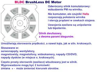
International Journal of Trend in Scientific Research and Development (IJTSRD) Volume 4 Issue 4, June 2020 Available Online: www.ijtsrd.com e-ISSN: 2456 – 6470 Speed-Torque Characteristics of BLDC Motor with Load Variations Ishita Gupta1, Akash Varshney2 1Scholar (PS&C), 2Assistant Professor, 1,2Department of Electrical Engineering, Babu Banarasi Das University, Lucknow, Uttar Pradesh, India ABSTRACT Nowadays, Brushless DC motors are in high demand due to its high efficiency and other significant features. As there is no use of brushes, this type of motor is having many advantages like high torque to inertia ratio, high speed, and power density and low cost compared to conventional brushed motors. This paper determines speed-torque characteristics of brushless dc motor with different load variation by using the proposed method and the developed controller. The variation in motor speed-torque characteristics for half load, full-load, and overloading condition is analyzed. This research has been conducted to analyze the model and compared with the simulation results which are very useful in studying the performance of motor system. The simulation is carried out in MATLAB/Simulink environment. KEYWORDS: BLDC Motor; PI Controller; Hall Sensors; Speed Torque Characteristics; MATLAB/SIMULINK How to cite this paper: Ishita Gupta | Akash Varshney Characteristics of BLDC Motor with Load Variations" Published in International Journal of Trend in Scientific Research and Development (ijtsrd), ISSN: 2456- 6470, Volume-4 | Issue-4, June 2020, pp.811-814, URL: www.ijtsrd.com/papers/ijtsrd31197.pdf Copyright © 2020 by author(s) and International Journal of Trend in Scientific Research and Development Journal. This is an Open Access article distributed under the terms of the Creative Commons Attribution License (CC (http://creativecommons.org/licenses/by /4.0) "Speed-Torque IJTSRD31197 BY 4.0) I. Brushless DC (BLDC) motor is an AC synchronous motor with permanent magnets on the rotor (moving part) and windings on the stator (fix part). Permanent magnets create the rotor flux and the energized stator windings create electromagnet poles. BLDC drives have received significant attention, owing to their high efficiency, electromagnetic interference and high mechanical reliability, fast response, weight, precise and accurate control, maintenance free operation, brushes construction and reduced size, torque delivered to motor size is higher making it useful in applications where space and weight are critical, thermal overload and under load protection is provided due to the absence of brushes. These motors are very popular in a wide variety of applications compared with a DC motor; the BLDC motor uses an electric commutator rather than a mechanical commutator so it is more reliable than the rotor’s magnetic flux. BLDC motor is driven by DC voltage and the magnetic field generated by the rotor rotate at the same frequency. According to the shape of their induced electromotive force it is further categorized into two types: sinusoidal and trapezoidal. The sinusoidal induced electromotive force waveform is associated with permanent synchronous motor and the trapezoidal electromotive force waveform is associated with this type of motor. Forced commutation is, therefore, implemented electronically with a power electronic amplifier that uses semiconductor switches to INTRODUCTION change current in the windings situated on the rotor. In such an arrangement, the magnets rotate continuously while the conductors remain stationary. These motors either incorporates internal or external position to sense the actual rotor position or its position can also be detected without sensors. BLDC motor are used in Aerospace, Consumer, Medical, Industrial Automation Instrumentation. These motors have many advantages over other motor drives and it is preferred for higher performance operations. The abrupt change in speed or load affects the performance of motor drive. But BLDC motor drive, as it has non-linear behaviour requires a controlled input so as to achieve the better performance. An accurate mathematical model is required for the design of controllers for the BLDC motor drives, simulation, controlling methods and parameter tuning methodology etc. For the same, modified/improved controller are required. PI controller provides easy tuning and thus is preferred in most of the industrial applications. In this paper the BLDC motor speed vs. torque characteristics for three different types of loadings i.e. half load, full-load, and overloading conditions are presented. Simulation results using MATLAB are established to validate system performances. II. SYSTEM DEVELOPMENT BLDC motors are also known as electronically commutated motors which are powered by direct-current (DC) electricity and commutation is controlledelectronically by the drive equipment and @ IJTSRD | Unique Paper ID – IJTSRD31197 | Volume – 4 | Issue – 4 | May-June 2020 Page 811
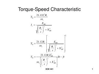
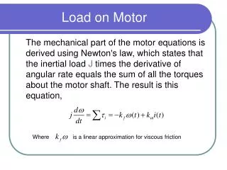
International Journal of Trend in Scientific Research and Development (IJTSRD) @ www.ijtsrd.com eISSN: 2456-6470 amplifier. Fig.1 shows the block diagram of the BLDC motor drive system used in the paper. The speed of the motor is compared with its reference value and the speed error is processed in proportional- integral controller. The outer loop is designed to improve the static and dynamic characteristics of the system. III. There are two torque parameters used to define a BLDC motor, peak torque and rated torque. During continuous operations, the motor can be loaded up to rated torque. This requirement comes for brief period, especially when the motor starts from stand still and during acceleration. During this period, extra torque is required to overcome the inertia of load and the rotor itself. The motor can deliver a higher torque up to maximum peak torque, as long as it follows the speed torque curve. As the speed increases to a maximum value of torque of the motor, continuous torque zone is maintained up to the rated speed after exceeding the rated speed the torque of the motor decreases. The stall torque represents the point on the graph at which the torque is maximum, but the shaft is not rotating. The no load speed is the maximum output speed of the motor. The speed is essentially controlled by the voltage, and may be varied by varying the supply voltage. The voltage is usually controlled by PWM and gives rise to a family of torque/speed characteristics in the boundaries of continuous and intermittent operation. Figure below shows the speed torque characteristics of a BLDC motor. The continuous limit is usually determined by heat transfer and temperature rise. The intermittent limit may be determined by the maximum ratings of semiconductor devices in the controller, or by temperature rise. SPEED-TORQUE CHARACTERISTICS Fig.1: Block diagram of BLDC motor drive The disturbance caused by the inner loop can be limited by the outer loop. The rotor position information supplied by the Hall Effect sensors of the BLDC motor. To control motor current, a proportional controller is used to supply proper switching pattern for inverter where three hall sensors are used. The brushless dc motor consists of four main parts which are as follows: 1.Inverter Circuit BLDC motors are fed by Voltage source inverters for its easy and wide range of speed control. It consists of two power semiconductor devices on each phase leg. Three phases are commutated for every 60 degree. Sensors work as a feedback element of the rotor position, so that synchronization is achieved between stator and rotor flux. 2.Hall Sensor Hall sensors are embedded into the stationary part of the motor. The hall sensors digital signals are used to sense the rotor position. It detects the change in magnetic field. The Hall sensors give high or low signal, when the rotor magnetic poles pass from it which indicates that the North or South Pole is passing near the sensors. Hall Effect sensors provide the portion of information need to synchronize the motor excitation with rotor position in order to produce constant torque. 3.PI Controller Conventional PI controller is used as a speed controller for recovering the actual motor speed to the reference. The reference and the measured speed are the input signals to the PI controller. The and determined by trial and error method for each set speed. The controller output is limited to give the reference torque.80%of the controller are PI controllers because they are facile and easy to comprehend. 4.BLDC Assembly The output of inverter circuit and reference input fed to BLDC Motor. The output of BLDCM is taken with the help of Bus Selector. The output of bus selector is as Stator Current, Stator back EMF, Rotor Speed and Electromagnetic torque. One of the outputs of PMSM is fed to Decoder/Gate block so that it decides the gate pattern of inverter circuit. The Rotor speed is fed back to the comparator to achieve the desired speed which is required. Fig.2: Speed-Torque characteristics IV. The proposed model has a flexible structure and enables users to change motor parameters easily unlike the state space models of BLDC Motor which are limited in their flexibility. Each subsystem determines the parameters of the motor. SIMULATION MODEL OF BLDC MOTOR values of the controller are Fig.3: BLDC Simulink Model with PI Controller Each part is modeled separately and integrated in overall simulation model. BLDC motor is modeled using electrical @ IJTSRD | Unique Paper ID – IJTSRD31197 | Volume – 4 | Issue – 4 | May-June 2020 Page 812
International Journal of Trend in Scientific Research and Development (IJTSRD) @ www.ijtsrd.com eISSN: 2456-6470 and mechanical mathematical equations.For Hall decoding block and gate triggering block logical models are developed according to hall signals (rotor position). The reference speed of 3000 rpm is used in the model and is compared with a feedback path and is then connected to a controller. A speed regulator is used to control the DC bus voltage. The outputs of the bridge inverter is applied to the permanent magnet synchronous motor (PMSM). The load torque provided to the machine shaft is step input of 3Nm. The system is first set to zero and then steps to its nominal value of 3Nm at time 0.1sec. Simulation of brushless DC motor with different load variations has been observed. V. SIMULATION RESULTS The speed-torque characteristics of BLDC motor under loading includes half load, full-load, and overloading are shown in Fig.4,5 and 6. It is also cleared that the machine has induced self-torque in the negative region after load removal which provides braking condition for BLDC motor. In case of loading conditions, the non-linearity behaviour of speed-torque characteristics of BLDC motor is maintained but machine shows erratic behaviour at the time of load removal. As the overloading exist, the speed-torque plot of BLDC reaches in the negative region with drastically change in the characteristics as shown in Fig.4-6. In the overloading conditions large oscillations has observed and BLDC motor shows jerky operation. This opens up a new scope for exploring the reasons for the jerky operation of the machine while removing the load; and to suggest mitigation technique for the same. Fig.5: Speed-Torque Characteristics Under Half Load Condition Fig.6: Speed-Torque Characteristics Under Over Load Condition VI. CONCLUSION A significant observation is made through the speed-torque characteristics of BLDC motor under the three types of load conditions using MATLAB/SIMULINK software with PI controller to analyze the overall behaviour of the machine. It is seen that the performance of the motor is better when the load is applied at half load condition than the full load and overload condition. REFERENCES [1]P. Suganthi, S. Nagapayithra and S. Umamaaheswari “Modelling and simulation of closed loop for BLDC motor”, IEEE conference on Emerging Devices and Smart System (ICEDSS 2017). Fig.4: Speed-Torque Characteristics Under Full Load Condition [2]Md. Rifat Hazari, Effat Jahan, Md. Tauhedull Islam Khan, “Design of a Brushless DC (BLDC) Motor Controller”, International Conference on Electrical Engineering and Information & Communication Technology (ICEEICT) 2014. [3]Shivraj S Dudhe and Archana G Thosar, “Mathematical Modelling and Simulation of Three Phase BLDC Motor Using MATLAB/Simulation”, International Journal of Advances in Engineering & Technology, Nov., 2014. @ IJTSRD | Unique Paper ID – IJTSRD31197 | Volume – 4 | Issue – 4 | May-June 2020 Page 813
International Journal of Trend in Scientific Research and Development (IJTSRD) @ www.ijtsrd.com eISSN: 2456-6470 [4]G. Prasad, N. Sree Ramya, “Modelling and Simulation Analysis of the Brushless DC Motor by using MATLAB” IJITEE Transaction, vol. 1, issue 5 October 2012. MATLAB GUI”, Proceedings of the IEEE Fifth International Conference on Fuzzy Systems and Knowledge Discovery, US, pp. 1403- 1407, 2011. [5]M. V. Ramesh, J. Amarnath, S. Kamakshaiah, “Speed Torque Characteristics of Brushless DC Motor in either direction on load using ARM controller”, Journal of Energy Technology and Policy,2011. [8]C. Gencer and M, Gedikpinar “Modelling and simulation of BLDCM using MATLAB”, Journals of Applied Science 2006. [9]S. Baldursson, “BLDC Motor Modelling and Control – A MATLAB / Simulink Implementation”, Master Thesis, May, 2005. [6]S. B. Ozturk and H. A. Toliyat, "Direct Torque and Indirect Flux Control of Brushless DC Motor," Mechatronics, IEEE/ASME Transactions on, vol. 16, pp. 351-360, 2011. [10]P. Pillay and R. Krishnan, “Modeling, Simulation and Analysis of a Permanent Magnet Brushless Dc Motor Drive," IEEE Trans. on Industry Applications, vol. 25, pp.274-279, March/April 1989. [7]Balogh Tibor, Viliam Fedak, Frantisek Durovsky., “Modeling and Simulation of the BLDC Motor in @ IJTSRD | Unique Paper ID – IJTSRD31197 | Volume – 4 | Issue – 4 | May-June 2020 Page 814