Download
1 / 53
1.21k likes | 2.16k Views
LNG Tank. Contains confidential proprietary and trade secrets information of CNH Industrial. Any use of this work without express written consent is strictly prohibited. LNG Tank. System presentation. LNG Tank. System presentation. Troubleshooting. Tank design.

E N D
LNG Tank • Containsconfidentialproprietary and tradesecrets information of CNH Industrial. Any use of this work without express writtenconsentisstrictlyprohibited.
LNG Tank System presentation
LNG Tank System presentation • Troubleshooting
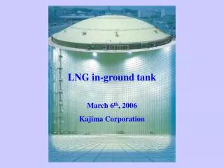
Tank design • System, made by Chart, has to be: • Safe • Easy to use • Easy maintainable • Simple • During re-filling LNG, the tank cools • Insulation is added to reduce any heating or pressure leakage.
Tank design • The internal tank (wrapped) is enclosed inside an external tank, and a vacuum is created between the walls • This combination of multi-layer insulation and the introduction of a vacuum is called superinsulation.
Heat exchanger • Heat exchanger to vaporize the LNG. • LNG runs through the internal coiled tubes • No pressure change LNG SUPPLY LINE TO ENGINE
Heat exchanger • Heat exchanger to vaporize the LNG. • LNG runs through the internal coiled tubes • No pressure change
Heat exchanger Troubleshooting • Leaks at threads Clean and reseal threads using proper procedures • Refer to VT-0030 • External cracks Replace heat exchanger • Cracks in the housing /at one of the coolant /LNG ports: • Loose or improper mounting • External damage • Unsecured tubing • Internal cracks • Will pressurize the engines cooling system Check heat exchanger mounting (vibration) and configuration. Check coolant inlet and outlet that must point up (horizontal mount). Check coolant inlet and LNG inlet that must be on the same end.
Economiser (regulator) • Maintains tank pressure to a preset level • When tank pressure is higher than the economiser internal spring pressure, an internal passageway is opened and gas flows to the supply line • Inlet and outlet filters included in the pipes
Economiser (regulator) Troubleshooting • Economizer seal leak • Pressure reduction in the tank and possible poor engine performance • Usually caused by dirties stuck under the economizer seat. • Economizer filters clogged • Results in high tank pressure, no engine performance difference replace filters • Economizer sticks closed • Results in high tank pressure, no engine performance difference. • Usually caused by sealant in economizer or plugged up economizer. • May cause higher than normal tank pressure / tank filling problems.
Economiser (regulator) Troubleshooting • Tubing for methane vapor to travel from economizer to outlet (use) tube. • Copper tubing (Flared) • Economizer tube will be frosted when engine is running and economizer is open
Refill nozzle • Pressure seal • Anti-shear • Flow rate 3,15 l/s • Fuel door with safety switch
Refill nozzle Troubleshooting • Fuel cover not closed completely or misaligned • Engine will not start Close door completely • Damaged or missing cover reed switch magnet • Engine will not start Replace magnet • Faulty reed switch • Engine will not start Replace switch • Testing reed switch: • With cover closed and magnet lined up with switch, resistance across Weather Pack pins should less than 1 Ω
Refill nozzle • Provides positive seal connection point for filling tank with LNG • The LNG tank receptacle can accept three different brands of filling nozzles Kodiak Macro-Tech JC Carter
Expansion tank • Expansion tank is separated by a calibrated hole. • During re-filling, the expansion tank remains mostly empty. • When LNG level is low, expansion tank is needed to create enough pressure to supply NP to engine. Expansion tank HEAT
Level sensor Components • Capacitance Tube • Capacitance Wire + Feed Through • Sender • Sender Cable • Vehicle Harness/System • Gauge
Level sensor Capacitance Tube • Capacitance is the ability to store electrical energy • A capacitor consists of two conducting surfaces (usually metal plates) separated by an insulating material. In Chart LNG tanks insulator is by LNG • The capacitance of the capacitor tells you how much charge it can store in the insulator when connected to a battery and is measured in units of farads • Chart LNG tanks are not electrically charged. • System measures only the potential of charge in picofarads (pF) • Liquids when used as a insulator will store a charge. • As the LNG levels increase, potential increases • As the LNG levels decrease, potential decreases. • This potential travels through the capacitance wire to the outside of the tank. • Capacitance tube is not serviceable
Level sensor Capacitance Wire + Feed Through • Carries the capacitance reading out of the inner tank and to the feed through connector • Soldered to the inner capacitance tube on the inside of the tank. • Is routed through vent tube and knuckle to the outside of the tank. • 20 gauge Teflon coated stranded wire. • Capacitance wire is soldered to the feed through. • Assembly end is covered with heat shrink and cap • Capacitance wire is not serviceable
Level sensor Sender + Cable • Measure capacitance following next chart Ground Signal
Level sensor Sender + Cable
Level sensor Sender + Cable • Sender converts capacitance reading into corresponding resistance/voltage value on green wire. It’s not serviceable and factory calibrated. • PIN • Red – 24 V to sender • Green – Signal reference • Black – Ground • Voltage signal • Standard Tank: 4.5 (full) - 0.4 (empty) V • Bonus Tank: 3.7 (full) - 0.4 (empty) V
Level sensor Sender + Cable Troubleshooting • Level gauge not correct value check the tank/sender ground wiring use the following procedure • Black – Ground
Level sensor • Fuel level read by no-detachable capacitive cable
LNG level sensor connection • Conductive pass through for capacitance traveling to the sender • Creates seal between LNG (inside tank) and atmospheric conditions (outside tank) • Mounts into tee on tank knuckle
LNG level sensor connection Troubleshooting • Loose or intermittent connection at outer feed through Remove heat shrink, repair/replace worn or damaged feed through cable • Shorted or open capacitance wiring De-fuel tank, remove feed through and repair wiring if possible • Leak at Feed Through threads De-fuel tank, remove and reseal feed through • LNG leaking at feed through seal De-fuel tank and replace feed through cable • Refer to VT-0042 for repair procedure steps
Dual pressure relief valve (Safety) Secondary 24 barRED CAP Main Valve16 barCONVEYED
Primary relief valve • The primary relief valve must be piped away to a safe location and pointed upward (vent stack) • Minimum recommended size is 13mm tubing • Tubing must be made of materials suitable for methane service • The vent stack must have a low point water drain • Note: The tank does not need to be de-fueled before removing this piping
Secondary Relief Valve • Safety device to ensure the tank does not over pressurize (24 bar) if the primary relief fails to operate • It has a RED cap in place to indicate if valve has discharged Caution: Tank must be de-fueled and pressure vented to 0 bar before performing repair procedures
Secondary Relief Valve Troubleshooting • If red cap is missing from secondary relief valve check the following: • Tank pressure • Pressure gauge for signs of damage • Check primary relief valve and entirepipe away for obstructions or kinked hoses • Best practice is to replace both valves • Refer to VT-0038 Caution: Tank must be de-fueled and pressure vented to 0 bar before performing repair procedures Note: If red cap is damaged or missing from secondary relief valve, remove unit from service
Dual pressure relief valve (Safety) Secondary 24 barRED CAP Main Valve16 barCONVEYED
Dual pressure relief valve (Safety) Troubleshooting • Sticks closed • Tank pressure could build higher than 16 bar and valve does not cycle De-fuel tank and replace valve • Sticks open Loss of pressure in tank and de-fuel tank and replace valve • Refer to VT-0038 Caution: Tank must be de-fueled and pressure vented to 0 bar before performing repair procedures Main Valve16 barCONVEYED Secondary 24 barRED CAP
Refill check valve • Protects tank against fuel leaks in case the fill connector is broken or damaged • Non-serviceable part
Refill check valve Troubleshooting • Leaks at threads • Remove, clean threads, and reseal using proper procedures • Refer to VT-0030 • Valve does not seal • Damaged or missing valve internal components Replace valve • Tank will not take fuel • Could be plugged or damaged fill check Replace valve Caution: Tank must be de-fueled and pressure vented to 0 bar before performing repair procedures
Service valves • Enable isolation of the tank for maintenance operations Vapor stop valve Liquid stop valve
Service valves • Enable isolation of the tank for maintenance operations Vapor stop valve Liquid stop valve
Service valves Troubleshooting • Valve is serviceable, but valve body is not, because it’s welded into the pipe. • Leak at valve stem Service valve using Installation Service Kit • Leak at bonnet threads Loose bonnet and use Installation Service Kit • Do not attempt to tighten bonnet only • Valve hard to turn Service valve using Installation Service Kit WELDED VALVE BODY
Excess flow valve • In case of overpressure/overflow, close LNG supply to heat exchanger
Excess flow valve Troubleshooting • Leaks on threads Remove part, clean and reinstall tape on straight threads and a new seal seal on 3/8” tube fitting connection • The excess flow valve can be replaced without de-fueling the tank. • Reset the excess flow valve • Close red handle fuel shut off valve. • Allow the excess flow valve to sit for a couple of minutes. • The small amount of LNG that leaks past the hard seat in the valve will eventually cause the pressure to equalize on both sides of the valve seat. This will allow the valve to return to the open position. • In a quiet area you may hear the valve reset.
In-line check valve • Provides a back-pressure of 0,138 bar (2 psi) on fluid supply line to help the economiser in rapidly reducing the pressure in the tank
In-line check valve Troubleshooting • Sticks open • Usually occurs due to contaminants in fuel De-fuel tank completely and replace the valve • Economiserdoes not pull pressure down in tank when engine is running • Tank at pressure above economizer setting after half of a tank of fuel has been used - • Economiseru-tube not frosted
Vent Connector • The vent connector allows to vent high vapor pressure back to the fuel station if necessary Note: The tank does not need to be de-fueled before replacing, but the grey valve must be closed and the vent line must be depressurized
Tank gauge Troubleshooting • Crack in face of gauge • Hurts Replace gauge • Water or moisture in gauge • Sealing damage Replace gauge • Gauge reads incorrectly • Weak spring Replace Gauge • Over pressurization check other pressure components • Gauge threads leaking Clean and reseal threads using Note: The pressure gauge cannot normally be replaced without de-fueling the tank
Fuel Shutoff Solenoid • At the outlet of the heat exchanger, shuts-off fuel flow to engine • NC valve with 2 PIN connection (weather pack connector) • Inlet & Outlet ports are marked (flow specific)
Fuel Shutoff Solenoid • Two pin Weather Pack connector • 24V Supply • Resistance 54 –64 Ω
Fuel Shutoff Solenoid Troubleshooting • Leaks at threads Clean and reseal threads using proper procedures • Refer to VT-0030 • Improper mounting Remount correctly • Damage to electrical circuit Check supply power and resistance to ground • Valve stuck closed • Low or no voltage Check supply power and resistance to ground • High resistance or shorted coil Check resistance
LNG Tank Secondary safety valve 24 bar Bleedvalve Main safety valve 16 bar Filling check valve Gauge Fill connector Economiser(regulator) In-linecheckvalve Expansiontank Liquid valve LNG -125 °c Excess flow valve Fuel level indicator and transmitter Fuel stopsolenoid valve Heat exchanger
LNG tank operation Gas flow • CONDITION: engine running and tank pressure above economizer set point Gaseous Fuel Flow
LNG tank operation Liquid flow • CONDITION: engine running and tank pressure at or below economizer set point Liquid Fuel Flow