Download
1 / 30
450 likes | 779 Views
Extrusion Revolve. ENGR 1182 SolidWorks 0 2. Today’s Objectives. Creating 3D Shapes from 2D sketches using: Extrusion Revolve SW02 In-Class Activity Extrude a Camera Revolve a Wheel SW02 Out-of-Class Homework Assignment. 3D Shapes.

E N D
ExtrusionRevolve ENGR 1182 SolidWorks 02
Today’s Objectives • Creating 3D Shapes from 2D sketches using: • Extrusion • Revolve • SW02 In-Class Activity • Extrude a Camera • Revolve a Wheel • SW02 Out-of-Class Homework Assignment
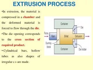
3D Shapes Basic methods of creating 3D shapes using a 2D sketch: • Extruding • “Stretching” the shape from its original 2D outline to a 3rd Dimension • Revolving • Creating a 3D object by drawing a 2D cross-section and revolving that around an axis
Extrusion ENGR 1182 SolidWorks 02
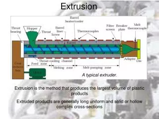
Extrusion • Closed Profile on a 2D Plane • Direction • Amount • First Extrusion • New 2D Planes Created • Add or Subtract Finished Product
Adding MaterialPositive Extrusion 2D Profile used to add material at a specified length 2D Profile extruded to next surface or to selected surfaces
Subtracting MaterialNegative Extrusions 2D Profile used to subtract material at a specified length 2D Profile used to cut to selected surfaces or through all
SolidWorks: Extrude Dialogue Box A Blind Extrusion is an Extrusion to a selected depth Reverse Direction Extrusion Options Depth Extruded Cut is for Negative Extrusions and contains many of the same options Direction 2 (if needed)
SolidWorks: Base Extrusion This profile is a nested profile and thus the final result only adds material between the outer and inner lines A base feature can be created by extruding a 2D sketch located on one of the original planes
SolidWorks: Sketching on Surfaces Once the first extrusion is completed new faces are available for sketching. Click the sketch button then select the 2D surface or plane that is necessary for the next step
SolidWorks: Extruded Cut Once the base feature is created, a 2D sketch can be drawn on one of the faces of the new object The depth can be determined by a numerical distance or other options for Extruded Cuts including: Through All and to Next Surface
SolidWorks: Special Feature Extrusions Extrusions can continue to be added and the resulting protrusion will be joined to the original base If a profile overlaps the original geometry then the two extrusions will merge to create one part
SolidWorks: Editing Features To edit any feature right click on the feature in the model tree • The dialogue window allows you to (from left to right, top to bottom): • Edit Feature • Edit Sketch • Suppress Feature • Roll Back • Hide • Zoom to Feature • Normal View to Feature • Change appearance (color)
Extrusion Wrap Up Extrusions • Positive Extrusion • stretch a 2D profile to 3D • Negative Extrusion • remove material from a 3D model (cut) • Geometries merge • Loops have to be CLOSED Homework Assignment SW02-OUT: Create shape shown using positive and negative extrusions. Shape is important, dimensions are not. Print off Isometric with Name, Seat Number, and Instructor. Shape in text Problem 6.4 (f)
In-Class Activity Design a camera with positive and negative extrusions. Be creative and feel free to create something original.
Revolve ENGR 1182 SolidWorks 02
Revolving • 2D Profile • Extents • Full Rotation • Degree • Axis of Rotation: • Attached – Closed Solid • Separated – Solid with Hole
Revolve Vs. Extrude • Revolve Complements Extrusion • Some Objects Difficult to Extrude • i.e. Cones, wheels • How would you create this object with extrude?
Positive Revolves Negative Revolves
SolidWorks: Revolution Axis Options in the Line tool can be chosen to create a construction line that will be used as a revolution axis
SolidWorks: Closed Profile SolidWorks preview allows the designer to select the correct options Example of a closed profile aligned with the center axis (created by using a construction line)
SolidWorks: Hollow Profile Example of a closed profile separated from the center axis (created by using a construction line) This example shows how to create a hollow revolve. This is helpful in the creation of wheels, etc.
Revolves Wrap Up Homework Assignment SW02-OUT: Create the following shape. Focus on shape and proportionality, not dimensions. • Positive Revolve • Make a 3D object • Negative Revolve • Remove material from a 3D object • Attached Rotation • Will produce a closed object • Separated Rotation • Will produce an object with a hole • Use construction lines for axes • Ensure validity of profile (entire sketch is on one side of revolution axis)
In-Class Activity Draw a wheel using a closed 2D profile similar to what is shown from Problem 6.4 (n)
Important Takeaways • 3D shapes can be created from 2D sketches using the extrusion and revolve features. • Negative extrusions and revolves are used to subtract material for a specified length. • Sketching on surfaces after creating the first extrusion is done by clicking the sketch button and selecting the 2D surface desired.
What’s Next? • Due Next Class: SW02 Out-of-Class HW • Before next class, you will read about geometric and dimensional constraint based modeling. • Geometric constraints constrain geometry based on normal orientations or relative to other parts of geometry. • Dimensional constraints are numerical values that constrain the size and location of geometry. • Take SolidWorks 3 Quiz on readings