Download
1 / 47
580 likes | 901 Views
Supported by . Physics of tokamak plasma start-up. D. Mueller. APS-DPP Meeting, Providence, RI Meeting October 29 - November 2, 2012. Normal aspect ratio tokamaks have inner coils for inductive start-up, spherical tokamaks have limited space.

E N D
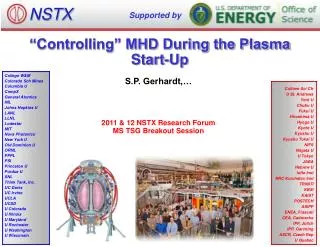
Supported by Physics of tokamak plasma start-up D. Mueller APS-DPP Meeting, Providence, RI Meeting October 29 - November 2, 2012
Normal aspect ratio tokamaks have inner coils for inductive start-up, spherical tokamaks have limited space • Generally focus is on the plasma current flattop, MHD events ELMs and disruptions • Start-up gets attention when it fails Now is the time to plan for start-up in • NSTX-U • JT60-SA • ITER Most of the planning revolves around what will happen during the flattop Recent start-up experience from • EAST and KSTAR, the first fully super-conducting tokamaks • JET ITER-like wall Long-pulse STs require non central solenoid start-up
Physics of tokamak plasma start-up Central solenoid inductive start-up and current ramp • Breakdown/avalanche • Impurity burn-through • Electron cyclotron radio-frequency assist • Examples from EAST and KSTAR • Early stage of plasma current ramp-up Start-up techniques without a central solenoid • Outer PF coil start-up • Electron Bernstein Wave start-up • Helicity injection • Coaxial helicity injection (CHI) • Plasma Guns
Inductive start-up can be divided into three phases, break-down/avalanche, burn-through and controlled ramp-up NSTX • Break-down, Te < 10 eV, j < 35 kA/m2Ip(NSTX)< 35 kA • Burn-through, 10 eV < Te < 100 eV, 30 kA/m2 < j < 300 kA/m2 • Controlled ramp-up Ip > 100 kA • Central solenoid provides voltage • Resistive heating or auxiliary power to heat and ionize low Z impurities • Vertical field to control plasma radius • Other Poloidal Field coils - shaping • Gas puffing for fueling Time (s)
Inductive start-up The central solenoid is supplied with a current in the desired direction of the plasma current before t0 At t0, the current is reduced towards zero by action of power supplies (assisted by IR drop) Resistance of coil or for superconducting coils by a resistor inserted into the circuit Leakage field Free electrons are always present, but can be supplemented by ECH, radiation, heated filaments, etc.
Breakdown in a gas, the Townsend avalanche • For parallel plate electrodes • If an electron produces a new electrons per meter then • dne = a nedx • ne = ne (0) eax • a is called the first Townsend coefficient 0.8 0.6 s(10-16cm2) 0.4 0.2 0 100 1000 10 Te(eV) From S.C. Brown, Intro. To Electrical Discharges in Gases, John Wiley and Sons, 1966. • Ionization cross-section peaks at about 50 eV and falls at high energy From http://physics.nist.gov/cgi-bin/Ionization/ion_data.php?id=HI&ision=I&initial=&total=Y
The voltage required for an avalanche depends upon the pressure distance product The Paschencurve (fromhttp://ja.wikipedia.org/wiki/ファイル:Paschen_Curves.PNG 106 105 H2 N2 Ar 104 V(volts) avalanche Ne 103 He 102 10-1 100 101 102 103 Pd(Torr•cm) • For NSTX, p ~ 5x 10⁻⁵ Torr and Vl ~ 2 V/turn • For NSTX then a ~ 10-2 /m • Connection length must be > 100 m, many toroidal transits • For E/p > 5X10³ V m-1 Torr-1, Te is high enough that thermal ionization is important • This limits Te to about 10 eV until ionization of the initial gas is nearly complete R. Papoular, Nuclear Fusion 16 (1976) 37.
Electrons must travel many ionization lengths before being lost if an avalanche is to occur 58.9 15.2 8.9 2.7 8.9 15.2 58.9 Field null at start-up in NSTX, includes eddy currents Similar plots can be made for every tokamak Lloyd et al., Nuclear Fusion, Vol.31. No.ll (1991) Parallel losses The stray field connection length, L ~ h BT/<dBz>h is the height of the machine <dBz> is the average transverse field • For NSTX BT ~ 4 kG, h ~ 2 m • <dBz> ~ 2.5 to 5.0 G • L ~ 3000 m The electron drift velocity, vdeparallel to the field lines is approximately 35 E/p (m/s) • Time to drift to wall ~ 6 ms • For ions, vdi= 0.9E/p, the time to drift to the wall ~ 150 ms • Secondary emission is unimportant Lloyd estimates the time to complete the avalanche process as 41/vde(a - L-1) • ~ 7 ms
Other losses that might stop avalanche from proceeding • If pressure is too low the density of neutrals will not be sufficient to provide electrons for the avalanche to continue • Guiding center drift velocity • vD = (1/2v^2 + v||2)/Rwce ; v^2 ~ v||2 ~ 3KTe/2m • vD ~4 to 40 m/s • Loss time ~ 25 -250 ms > avalanche time • Taken together for a wide range of devices • VL = 2 to 30 V/turn, E = 0.3 to 2 V/m, with stray fieldsBz/BT ~ 10-3 over much of the vessel • p = 1-10 x 10-5Torr • E/p = .4 to 3 X 10⁴ V m-1 Torr-1 • Time for avalanche to occur ~ 2 - 50 ms • JET found E • BT/dBz > 103 V/m • A. Tanga, et al.in “Tokamak Start-up” H. Knoepfel. Plenum Press, NY (1985) • Consistent with NSTX and DIII-D I.H.Hutchinson, J.D.StrachanNucl. Fusion 14 649(1974)
Avalanche proceeds until electron-ion collisions are the dominate process compared to electron-neutral collisions Electron-neutral and electron-ion collision rates equal when ne ~ 0.1 n0 Current density is j = g n0evd where g is the H or D ionization fraction • j ~ 15-40 kA m-2 • Ip ~ 5 - 10 kA for NSTX, ~ 20 kA for JET • For Ip= 10 kA a = 0.5 m, poloidal field m0Ip/2pa ~ 40 G • Comparable to stray fields • At end of avalanche phase, g~ 0.5, Coulomb collisions dominate j ~ 160 kA m-2 this agrees with Ip ~ 200-400 kA at end of avalanchefor JET Until ionization is nearly complete, Te is limited below 10 eV Later Te can be limited by low Z impurity radiation to < 100 eV until the impurities are ionized (latter phase is called burn-through) • Burn-through can be a sticking point when either the influx of impurities liberated from the wall or the density is too high • For NSTX this can happen at Ip = 100 to 300 kA and limit the current ramp-rate during start-up so discharge fails
Database from JET show good agreement between Lloyd’s estimate of the avalanche time and the peak time of Ha The JET ITER-like wall is comprised of Tungsten and berrylium Time of peak Ha(s) tLloyd = 41/(vde(a - L-1)) Using the best estimate of L Failed discharges do not deviate from others during the avalanche failure is generally not in the avalanche process P. deVries, 25thIAEA,SanDiego, EXD4-2(2012)
Physics of tokamak plasma start-up Central solenoid inductive start-up and current ramp • Breakdown/avalanche • Impurity burn-through • Electron cyclotron radio-frequency assist • Examples from EAST and KSTAR • Early stage of plasma current ramp-up Start-up techniques without a central solenoid • Outer PF coil start-up • Electron Bernstein Wave start-up • Helicity injection • Coaxial helicity injection (CHI) • Plasma Guns
It has been known for a long time that Low Z impurity radiation can cause excessive energy losses at low Te f(Z,Te)(ergs•cm-3•s-1) 1 1 1 10 10 10 102 102 102 10-2 10-2 10-2 10-1 10-1 10-1 10. Radiated power Prad ~ neSnZf(Z,Te) Power supply E2/h • Coronal equilibrium 3% O with ne of 3 X 10¹⁹ m-3 VL (150V) • Radiation Barrier: The radiated power must be less than the input power or the discharge will cool and collapse • High Z materials have lower sputtering yields at low T so are less important at start-up q-limit j2h Power(W/cm3) 1.0 PRAD From Hawryluk and Schmidt, 1976 Nucl. Fusion 16 775 0.1 5 10 20 50 100 Te(eV) From D.E. Post et al., At. Data Nucl. Data Tables 2, 400, 1977
Impurity burn through has presented difficulties to most tokamaks, particularly early in the machine’s operation • Solutions employed to minimize impurity influx include • High temperature vacuum bake (to 350° to remove water and complex hydrocarbons) • Glow discharge cleaning (removes oils and He GDC removes H/D) • Boronization (various application techniques, reduces O) • Lithium coatings (Reduces C, O and H/D) • Ti gettering (coats surfaces reduces O, H/D and C) • Use of metal walls can limit the source of low Z impurities (ITER plans include Be which radiates significantly less than C or O) • Alternatively auxiliary heating can be employed to burn through the low Z impurities and heat the plasma
Recently H-T Kim developed a model (DYON) that uses a dynamic recycling and sputtering model for JET start-up • Deuterium confinement time tD • 1/tD = 1/tD,|| + 1/tD,^ • The rotational transform will increase the effective distance to the wall as Ip increasesso • L(t) ~ (0.25 a(t) BT/Bz(t) exp(Ip(t)/Iref)) • Irefis chosen so the plasma’s poloidal field exceeds the stray field • The deuterium confinement time due to parallel particle loss is • tD,|| = L(t)/Cs where Cs is the sound speed (Te + Ti)1/2/mD • For Perpendicular transport use Bohmdiffusion • A dynamic recycling coefficient is used for deuterium • Physical sputtering and a simple chemical sputtering model is used: O C+O and C + 4D CD4 Hyun-Tae Kim, W. Fundamenski, A.C.C. Sips et al.Nucl. Fusion 52 (2012) 103016
Model results agree well with experiment and demonstrate the importance of including the parallel loss • Blue lines indicate simulation results • Red curves on the plots are JET data C-II 1 MA Ip • The temporal agreement for the C-II emission gives confidence that impurities are being well-modeled • The time evolution of the C charge states in the model indicates from 0.15 s on C is fully ionized • The early density discrepancies may be due to geometrical effects • This recent start-up model is self-consistent and includes the important time evolution of impurities from the wall due to sputtering by plasma ions 20 V VLoop 2 MW PRad 400 eV Te 4 X 10¹⁸/m2 ne 0 0.5 Time(s) Hyun-Tae Kim, W. Fundamenski, A.C.C. Sips et al.Nucl. Fusion 52 (2012) 103016
The density at the time of burn-through depends on fill pressure, and the radiated power depends on the wall • For discharges with similar start-up conditions Vloop =12 V, E = 0.8 V/m • At tBURN the density is prefill pressure + some extra for C-Wall • At tBURN radiated power is a steep function of density for C-Wall • No non-sustained breakdowns with ILW due to deconditioning P. deVries, 25th IAEA, SanDiego, EXD4-2(2012)
Physics of tokamak plasma start-up Central solenoid inductive start-up and current ramp • Breakdown/avalanche • Impurity burn-through • Electron cyclotron radio-frequency assist • Early stage of plasma current ramp-up • Examples from EAST and KSTAR Start-up techniques without a central solenoid • Outer PF coil start-up • Electron Bernstein Wave start-up • Helicity injection • Coaxial helicity injection (CHI) • Plasma Guns
Superconducting tokamaks have low loop voltage which can be marginal on ITER for breakdown and burn-through • Power supply cost, eddy current heating in the superconducting coils, vacuum vessel and cryo-stat combine to place limits on the applied electric field • For ITER, E ~ 0.3V/m, the low end of successful breakdown • EAST and KSTAR insert resistors into the coil circuits to produce higher voltage for breakdown • All 3 have less ohmic power to heat the plasma and ramp the plasma current than conventional tokamaks • Electron Cyclotron Radiofrequency Heating (ECRH) can lower the voltage required for breakdown by a factor of about two • ECRH can provide power to heat the plasma • This is especially important during burn-through when Ip is low and ohmic power is limited
Lloyd used a 0-D model of power balance during the start-up on ITER to assess the need for additional power • Electron power balance • Ion power balance • Particle balance This 0-D model handles impurities by assuming they are a fixed fraction of the deuterium density It uses deuterium recycling coefficient R=1.01 B Lloyd, P G Carolan and C D Warric, Plasma Phys. Control. Fusion 38 (1996) 1627–1643.
Conclusions for the 0-D model for start-up is that start-up on ITER will be more robust with additional power • Zero-dimensional modeling of ITER start-up scenarios indicates that for inductive only start-up: • Burn-through with 2% Be impurity is possible for low fill pressure 1.5X10¹⁷/m3 (2X10⁻⁶ Torr), post avalanche density < 1.5 X10¹⁸/m3 • However for 5% Be or a higher fill pressure failure is likely • Addition of auxiliary power in the form of Electron Cyclotron Resonant Heating (ECRH) improves power margin • With 2 MW of absorbed ECRH 5% Be impurity is allowable with a post avalanche density of 5 X10¹⁸/m3 • but not for 2% C • For 5% C and the same density 5 MW of absorbed ECRH is required for robust start-up • ITER plans now include several MW of ECRH • Now we will move on to experience with ECRH and start-up on JET with ITER-like wall which provide useful data for further insight B Lloyd, P G Carolan and C D Warric, Plasma Phys. Control. Fusion 38 (1996) 1627–1643.
ECRH has been used on many devices to provide pre-ionization and electron heating during start-up • 2nd Harmonic X-Mode (E^B) and fundamental O-Mode (E||B) launched from the low field side can access the plasma • Use of ECH lowers the required field for breakdown below 0.3 V/m 2wce Fast-framing camera of CIII emission during 2nd harmonic ECH in DIII-D G. L. Jackson PhysPlasmas_17_056116 (2010)
Progression of discharge phases during ECRH start-up in DIII-D • Avalanche and expansion phases have low Ip • Current channel forms at 20-60 kA evidenced by increase it Te • Burn-through follows with additional heat from ECH
Physics of tokamak plasma start-up Central solenoid inductive start-up and current ramp • Breakdown/avalanche • Impurity burn-through • Electron cyclotron radio-frequency assist • Examples from EAST and KSTAR • Early stage of plasma current ramp-up Start-up techniques without a central solenoid • Outer PF coil start-up • Electron Bernstein Wave start-up • Helicity injection • Coaxial helicity injection (CHI) • Plasma Guns
Causes of discharge failure are not always obvious EAST First Plasma CCD image just after break-down suggests failure to burn-through • The start-up of the first plasma on EAST • Early attempts disrupted at Ip ~ 35 kA at 70-100 ms, unclear why • The breakdown resistors were in the circuit for 100 ms • Mutual from central coils exceeded vertical field power supply capability (which have since been upgraded) • Model predicted more negative vertical field than achieved • Camera images indicate plasma was at large R • Failure was due to too small vertical field • Shortened the breakdown resistor time to 50 ms From J. Leuer, et al., Fusion Science and Tech.. 57 2010
For all tokamaks it is essential to apply the proper vertical field and to have a vertically and radially stable field pattern Vertical field (circular plasma) Radial Field Field index n • KSTAR has ferromagnetic material in the coil jackets • Higher vertical field at small R which increases field index • Important effect for field null and low Bz • Plasma start-up variability, particularly smaller R, sometimes resulted in radial instability before the effect of magnetic material was considered • Modifying the start-up field pattern to account for ferromagnetic effects produced a stable configuration • Greatly improved reliability when implemented in 2010 and allowed ohmic start-up without ECH for the first time in KSTAR • J. Kim, Nucl. Fusion 51 (2011) 083034
Physics of tokamak plasma start-up Central solenoid inductive start-up and current ramp • Breakdown/avalanche • Impurity burn-through • Electron cyclotron radio-frequency assist • Examples from EAST and KSTAR • Early stage of plasma current ramp-up Start-up techniques without a central solenoid • Outer PF coil start-up • Electron Bernstein Wave start-up • Helicity injection • Coaxial helicity injection (CHI) • Plasma Guns
So far neglected a discussion of plasma density except when discussing Kim’s and Lloyd’s modelling • With graphite wall generally the density rises with Ip, even with no additional fueling (Blue trace) • With JET-ILW and no additional fueling the density falls (Green trace) • Lower ne higher Tebroader current profiles that result in instability • Gas puffing is effective to fuel the plasma and target plasmas can be achieved(Black trace) P. deVries, 25th IAEA, SanDiego, EXD4-2(2012)
The choice of plasma growth strategy determines the current density profile evolution which influences stability JET • Constant q growth realizes fully evolved j(r) profiles earlier and has higher internal inductance, li • Full aperture scenario has broaderj(r) and minimizes li • Each strategy is affected by ramp-rate, impurities and heating power and timing typically, dIp/dt < 0.5 MA/s Ip Internal inductance q-95 Rout Wesson, J., et al., Nucl. Fusion 29 (1989) 641.
ITER strategy for plasma growth has evolved from small aperture growth to a large-bore start-up that diverts earlier Small aperture growth • Small bore start-up scenario; q ~ constant growth, diverts at high current • Long Ip ramp-up time due to low loop voltage • Limited on outboard surface – heating issue • Facilitates current penetration – early sawteeth • Large bore plasma that diverts at lower Ip reduces heating of limiter • Large-bore start-up studies on DIII-D indicate less heating of limiter and li closer to ITER target and has now been adopted by ITER G. Jackson, Nucl. Fusion 48 (2008) 125002
Physics of tokamak plasma start-up Central solenoid inductive start-up and current ramp • Breakdown/avalanche • Impurity burn-through • Electron cyclotron radio-frequency assist • Examples from EAST and KSTAR • Early stage of plasma current ramp-up Start-up techniques without a central solenoid • Outer PF coil start-up • Electron Bernstein Wave start-up • Helicity injection • Coaxial helicity injection (CHI) • Plasma Guns
Central solenoid is well understood and works well, but there are reasons to consider other start-up techniques D.A. Gates et al. Fusion Engineering and Design 86 (2011) 41–44 Elimination of a conventional solenoid is required to achieve low aspect ratio at small device size for fusion nuclear applications If non-inductive current drive could support a steady state reactor, an alternative start-up technique could support elimination of the solenoid Having small or no solenoid could also help reduce conventional tokamak reactor size and cost With an iron core the plasma physics is similar, but engineering issues remain
All inductive start-up strategies face the same issues as using a central solenoid, but the emphasis may differ • DIII-D, JT60, MAST, NSTX and others have demonstrated inductive start-up without use of the central coils • A good field null with a stabilizing poloidal field pattern must be provided while at the same time ramping the outer coils to produce flux • Example from DIII-D • Coil currents and plasma current for outer PF start-up • Used ECRH for plasma initiation and burn-through • Only the labeled coils participate • Diverting plasma requires positive current in divertor coils From J. Leuer, Nucl. Fusion 51 (2011) 063038
Physics of tokamak plasma start-up Central solenoid inductive start-up and current ramp • Breakdown/avalanche • Impurity burn-through • Electron cyclotron radio-frequency assist • Examples from EAST and KSTAR • Early stage of plasma current ramp-up Start-up techniques without a central solenoid • Outer PF coil start-up • Electron Bernstein Wave start-up • Helicity injection • Coaxial helicity injection (CHI) • Plasma Guns
Of the candidate RF start-up strategies for the ST, so far Electron-Bernstein Wave (EBW) is the most promising The acceleration of electrons in a preferential direction by RF waves can be used for start-up Lower Hybrid Current Drive start-up to 100 kA was demonstrated on PLT in the early 80s. Start-up by ECH on DIII-D, TS2 and LATE EBW has been used on MAST to start-up the plasma current to 33 kA using 100 KW • EBW is an electrostatic wave that can exist only in a plasma • It can be produced by mode-conversion of X-Mode electron-cyclotron frequency waves at the upper hybrid resonance (UHR)
EBW can be produced by mode conversion of X-Mode waves in ECRF launched from the high field side From V. Shevchenko, EC-15 Joint Workshop, 2008, Yosemite, CA, USA MAST solution is to launch O-Mode from the low field side (LFS) • O-Mode wave at 28 Ghz is not strongly damped (<2% absorption) below the cut off density of about 1X10¹⁹/m3 • A grooved reflector (polarizing mirror) cut into the central column converts the O-Mode to X-Mode wave.
28 GHz breakdown with O-Mode launch with toroidal field and 1mT vertical field in MAST, and ray tracing of EBW Gas puff wce Sketch of ray-tracing modelling of EBW CD plasma initiation O-mode, Ip≈ 5 kA EBW ^ UHR Sign of n|| from projection of k along poloidal field (Bp) Bp changes sign when closed flux forms V. Shevchenko, EC-15 Joint Workshop, 2008, Yosemite, CA, USA See Laqua, Plasma Phys. Control. Fusion 49 (2007) R1–R42
MAST EBW start-up to 33 kA with 100 kW ECRF using vertical shifts to provide co-current in both open- and closed-fields #18240, 98ms Ip = 32kA, non-solenoid V.F. Shevchenko et al. Nucl. Fusion 50 (2010) 022004 (5pp) Proportion co/counter EBW CD depends on fraction above/below the midplane Plasma shifted up during open field line period Plasma shifted at the time closed field lines appear to maintain co-current drive
Physics of tokamak plasma start-up Central solenoid inductive start-up and current ramp • Breakdown/avalanche • Impurity burn-through • Electron cyclotron radio-frequency assist • Examples from EAST and KSTAR • Early stage of plasma current ramp-up Start-up techniques without a central solenoid • Outer PF coil start-up • Electron Bernstein Wave start-up • Helicity injection • Coaxial helicity injection (CHI) • Plasma Guns
Transient CHI current formation achieved by biasing inner vs. outer vessel to drive expanding helical current channel Gas injected at bottom of device, breakdown proceeds via Townsend avalanche along helical field connecting inner and outer vessel with many wraps the toroidal current can be 100 times injector current Bubble burst condition: When Iinj > 2 inj02d2ITF) Plasma fills vessel Reconnection occurs when injector current is reduced to zero closed flux surfaces R. Raman, Nucl. Fusion 51 (2011) 113018 (8pp) D. Mueller. Fusion Science and Technol. 52 2007
Transient CHI start-up must be followed by another means of current drive - so far only inductive drive has been available Comparison of CHI initiated discharge ( in red) with only inductive current drive (in blue) Neutral beam heated L-Mode discharges initiated with CHI use about 40% less inductive flux to reach 1 MA. Discharges with high Te early ramp to higher currents From Nelson, Nucl. Fusion 51 (2011) 063008
Physics of tokamak plasma start-up Central solenoid inductive start-up and current ramp • Breakdown/avalanche • Impurity burn-through • Electron cyclotron radio-frequency assist • Examples from EAST and KSTAR • Early stage of plasma current ramp-up Start-up techniques without a central solenoid • Outer PF coil start-up • Electron Bernstein Wave start-up • Helicity injection • Coaxial helicity injection (CHI) • Plasma Guns
Plasma guns have been employed on PEGASUS to inject helicity and provide start-up plasmas Relaxation Limit High Iinj, low w From Eidietis, J. Fusion Energy (2007)26:43-46 Helicity input rate High Vinj, Ainj From Battaglia, Nucl. Fusion 51 (2011) 073029 Images of plasma gun startup with gun located near the center (top) and outside (lower) of the Pegasus a) filaments b) Merging c) Relaxation Gun location is flexible Could be withdrawn after start-up From Battaglia, J Fusion Energy (2009) 28:140–143
Plasmas initiated with plasma guns on PEGASUS have been ramped to over 100 kA with < 4 kA of gun current 44 • Plasma initiated with plasma guns can be ramped to higher current by induction. • 150 kA in this example was achieved with half the inductive flux required for a purely inductively driven plasma • Demonstrated initiation and ramp-up Ip > 100 kA • Current multiplication >25 Battaglia, PRL 102, 225003 (2009)
Inductive start-up with ECH is well understood and promising non-inductive start-up techniques exist for STs Townsend avalanche and burn-through have been modeled self-consistently ECRH to both assist the avalanche and heat to burn through low Z impurities Low aspect ratio tokamaks have little space for a central solenoid so the usual inductive technique is problematic Possible alternatives to solenoidal start-up • Outer PF start-up • Electron Bernstein Wave • Coaxial helicity injection • Plasma guns to inject helicity Demonstrated start-up from zero to significant current Well-positioned for start-up of ITER
Acknowledgements Thanks to Gary Jackson – General Atomics Peter deVries - JET Victor Schevchenko - MAST Gary Taylor - PPPL Michael Bell – PPPL Roger Raman – Univ. of Washington Ray Fonck – Univ. of Wisconsin Devon Battaglia – PPPL Walter Guttenfelder – PPPL David Gates - PPPL and Jon Menard – PPPL for providing me with material, for valuable insights, and for useful discussions. Work supported by U.S. DOE Contract No. DE-AC02-09CH11466
References to illustrative work Inductive start-up • S.C. Brown, Intro. To Electrical Discharges in Gases, John Wiley and Sons, 1966. • R. Papoular, Nucl. Fusion 16 (1976) 37 • B. Lloyd et al., Nucl. Fusion, Vol.31. No.ll (1991) • A. Tanga, et al. in “Tokamak Start-up” H. Knoepfel. Plenum Press, NY (1985) • I.H.Hutchinson and J.D.StrachanNucl. Fusion 14 649(1974) • E.A. Lazarus et al. Nucl. Fusion 38 1083 (1998) • P. deVries, 25thIAEA,SanDiego, EXD4-2(2012) • R. Hawryluk and J. Schmidt, 1976 Nucl. Fusion 16 775 • From D.E. Post et al., At. Data Nucl. Data Tables 2, 400, 1977 • Hyun-Tae Kim et al. Nucl. Fusion 52 (2012) 103016 • J. Kim, Nucl. Fusion 51 (2011) 083034 • J. Leuer, et al., Fusion Science and Tech.. 57 2010 • J. Leuer, Nucl. Fusion 51 (2011) 063038 ECRH • B Lloyd, P G Carolan and C D Warric, Plasma Phys. Control. Fusion 38 (1996) 1627–1643. • G. L. Jackson et al. Phys. Plasmas_17_056116 (2010) • G.L. Jackson et al. Fus. Sci. & Technology 50 (2010) 27 • T. Yoshinaga et al. PRL 96, 125005 (2006) • A. Ejiri et al. Nucl. Fusion 46 (2006) 709–713 EBW • V. Shevchenko, EC-15 Joint Workshop, 2008, Yosemite, CA, USA • Laqua, Plasma Phys. Control. Fusion 49 (2007) R1–R42 • V.F. Shevchenko et al. Nucl. Fusion 50 (2010) 022004 (5pp) • C.B. Forrest et al. Phys. Plasma 7, 1352 (2000) CHI • R. Raman et al. Nucl. Fusion 51 (2011) 113018 (8pp) • D. Mueller et al. Fusion Science and Technol. 52 2007 • B.A. Nelson et al. Nucl. Fusion 51 (2011) 063008 Plasma guns • Battaglia, J Fusion Energy (2009) 28:140–143 • Battaglia, Nucl. Fusion 51 (2011) 073029 • Eidietis, J. Fusion Energy (2007)26:43-46 • Battaglia, PRL 102, 225003 (2009) Other • F.C. Jobes PRL 52 12, 1005 (1984) • F.C. Jobes et al. in , et al. in “Tokamak Start-up” H. Knoepfel. Plenum Press, NY (1985) • D.A. Gates et al. Fusion Engineering and Design 86 (2011) 41–44