Download
1 / 21
580 likes | 1.31k Views
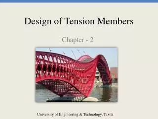
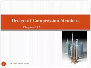
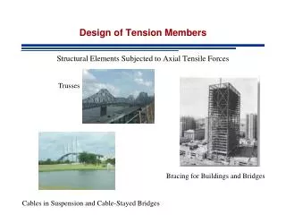
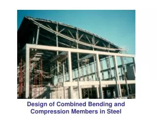
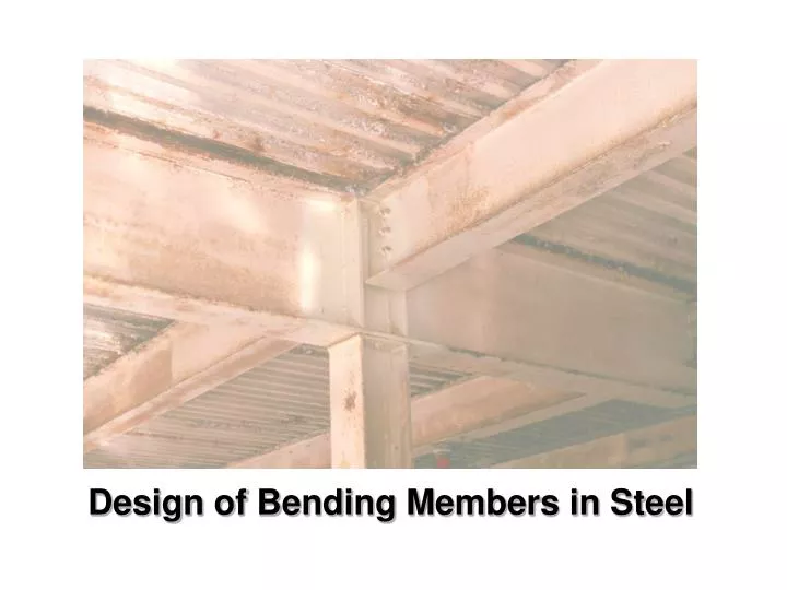
Design of Bending Members in Steel. Steel wide flange beams in an office building. Composite Steel-Concrete Girders. An example of curved steel beams. German Historical Museum. Steel Girders for Bridge Decks. Sea to sky highway, Squamish. Cantilevered arms for steel pole.

E N D
An example of curved steel beams German Historical Museum
Steel Girders for Bridge Decks Sea to sky highway, Squamish
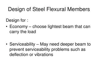
What can go wrong ? STEEL BEAMS: • Bending failure • Lateral torsional buckling • Shear failure • Bearing failure (web crippling) • Excessive deflections
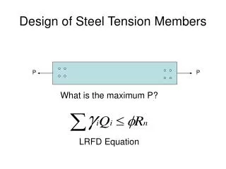
Bending Strength Linear elastic stresses y M Design Equation: Where Fb is the characteristic bending strength For steel this is Fb = Fy For timber it is Fb = fb (KDKHKSbKT)
Fy Fy Ac C My Mp a T At Plastic moment capacity of steel beams Yield moment Plastic moment Which is the definition of the plastic section modulus Z Z can be found by halving the cross-sectional area and multiplying the distance between the centroids of the two areas with one of the areas This is also called the first moment of area So, when do we use the one or the other ??
Steel beam design equation For laterally supported beams (no lateral torsional buckling) Mr = Fy Z for class 1 and 2 sections Mr = Fy S for class 3 sections where = 0.9
Elastic buckling: Mu = ωπ / Le √(GJ EIy ) + (π/L)2EIy ECw Moment gradient factor Torsional stiffness Lateral bending stiffness Warping stiffness y y Le Δx x Δy θ x x y y Lateral torsional buckling
Mmax = My for class 3 or Mp for class 1 and 2 Mmax 0.67Mmax 1.15 Mmax [1- (0.28Mmax/Mu)] Mu Moment resistance of laterally unsupported steel beams Mr / Le
A τ τ y A y d b=w d τmax = V(0.5A)(d/4) (bd3/12)b =1.5 V/A τmax ≈ V/Aw =V/wd N.A. N.A. b Shear stress in a beam
Shear design of a steel I-beam Vr = φ Aw 0.66 Fy for h/w ≤ 1018/√Fy = 54.4 for 350W steel w This is the case for all rolled shapes d h For welded plate girders when h/w ≥ 1018/√Fy the shear stress is reduced to account for buckling of the web (see clause 13.4.1.1) Aw = d.w for rolled shapes and h.w for welded girders
N+10t w N+4t k N Bearing failures in a steel beam For end reactions For interior reactions
Deflections • A serviceability criterion • Avoid damage to cladding etc. (Δ ≤ L/180) • Avoid vibrations (Δ ≤ L/360) • Aesthetics (Δ ≤ L/240) • Use unfactored loads • Typically not part of the code • Δ