Download
1 / 35
360 likes | 384 Views
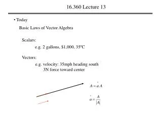
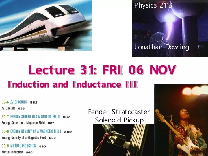
Physics 2113 Jonathan Dowling. Lecture 31: FRI 06 NOV. Induction and Inductance III. Fender Stratocaster Solenoid Pickup. dA. Changing B-Field Produces E-Field!. B. We saw that a time varying magnetic FLUX creates an induced EMF in a wire, exhibited as a current.

E N D
Physics 2113 Jonathan Dowling Lecture 31: FRI 06 NOV Induction and Inductance III Fender Stratocaster Solenoid Pickup
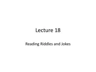
dA Changing B-Field Produces E-Field! B • We saw that a time varying magnetic FLUX creates an induced EMF in a wire, exhibited as a current. • Recall that a current flows in a conductor because of electric field. • Hence, a time varying magnetic flux must induce an ELECTRIC FIELD! • A Changing B-Field Produces an E-Field in Empty Space! To decide direction of E-field use Lenz’s law as in current loop.
magnetic field lines electric field lines Solenoid Example B • A long solenoid has a circular cross-section of radius R. • The magnetic field B through the solenoid is increasing at a steady rate dB/dt. • Compute the variation of the electric field as a function of the distance r from the axis of the solenoid. Next, let’s look at r > R: First, let’s look at r < R:
i i Added Complication: Changing B Field Is Produced by Changing Current i in the Loops of Solenoid! E(r) r r = R Solenoid Example Cont. B E
Summary Two versions of Faradays’ law: • A time varying magnetic flux produces an EMF: • A time varying magnetic flux produces an electric field:
30.7: Inductors and Inductance: An inductor (symbol ) can be used to produce a desired magnetic field. If we establish a current i in the windings (turns) of the solenoid which can be treated as our inductor, the current produces a magnetic flux FBthrough the central region of the inductor. The inductance of the inductor is then The SI unit of inductance is the tesla–square meter per ampere (T m2/A). We call this the henry (H), after American physicist Joseph Henry,
Inductors: Solenoids Inductors are with respect to the magnetic field what capacitors are with respect to the electric field. They “pack a lot of field in a small region”. Also, the higher the current, the higher the magnetic field they produce. CapacitanceC how much potential for a given charge: Q=CV InductanceL how much magnetic flux for a given current: Φ=Li Using Faraday’s law: Joseph Henry (1799-1878)
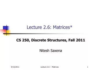
loop 1 loop 2 (30–17)
i (a) 50 V (b) 50 V Example • The current in a L=10H inductor is decreasing at a steady rate of i=5A/s. • If the current is as shown at some instant in time, what is the magnitude and direction of the induced EMF? • Magnitude = (10 H)(5 A/s) = 50 V • Current is decreasing • Induced EMF must be in a direction that OPPOSES this change. • So, induced EMF must be in same direction as current
The RL circuit • Set up a single loop series circuit with a battery, a resistor, a solenoid and a switch. • Describe what happens when the switch is closed. • Key processes to understand: • What happens JUST AFTER the switch is closed? • What happens a LONG TIME after switch has been closed? • What happens in between? Key insights: • You cannot change the CURRENT in an inductor instantaneously! • If you wait long enough, the current in an RL circuit stops changing! At t = 0, a capacitor acts like a solid wire and inductor acts like break in the wire. At t = ∞ a capacitor acts like a break in the wire and inductor acts like a solid wire.
30.9: RL Circuits: If we suddenly remove the emf from this same circuit, the flux does not immediately fall to zero but approaches zero in an exponential fashion:
RC vs RL Circuits In an RL circuit, while fluxing up (rising current), E = Ldi/dt and the loop rule mean: • magnetic field increases from 0 to B • current increases from 0 to E/R • voltage across inductor decreases from -E to 0 In an RC circuit, while charging, Q = CV and the loop rule mean: • charge increases from 0 to CE • current decreases from E/R to 0 • voltage across capacitor increases from 0 to E
10 Ω 9 V 10 H ICPP Immediately after the switch is closed, what is the potential difference across the inductor? (a) 0 V (b) 9 V (c) 0.9 V • Immediately after the switch, current in circuit = 0. • So, potential difference across the resistor = 0! • So, the potential difference across the inductor = E = 9 V!
40 Ω 3 V 10 Ω 10 H ICPP • Immediately after the switch is closed, what is the current i through the 10 Ω resistor? (a) 0.375 A (b) 0.3 A (c) 0 • Immediately after switch is closed, current through inductor = 0. Why??? • Hence, current through battery and through 10 Ω resistor is i = (3 V)/(10 Ω) = 0.3 A • Long after the switch has been closed, what is the current in the 40 Ω resistor? (a) 0.375 A (b) 0.3 A (c) 0.075 A • Long after switch is closed, potential across inductor =0. Why??? • Hence, current through 40 Ω resistor i = (3 V)/(10 Ω) = 0.375 A (Par-V)
Fluxing Up The Inductor • How does the current in the circuit change with time? i i(t) Fast = Small τ E/R Slow= Large τ Time constant of RL circuit: τ = L/R
i i(t) Exponential defluxing E/R Fluxing Down an Inductor The switch is at a for a long time, until the inductor is charged. Then, the switch is closed to b. What is the current in the circuit? Loop rule around the new circuit walking counter clockwise:
i Power delivered by battery = power dissipated by R Inductors & Energy • Recall that capacitors store energy in an electricfield • Inductors store energy in a magnetic field. P = iV = i2R + (d/dt) energy stored in L
Inductors & Energy Magnetic Potential Energy UB Stored in an Inductor. Magnetic Power Returned from Defluxing Inductor to Circuit.
10 Ω 9 V 10 H Example • The switch has been in position “a” for a long time. • It is now moved to position “b” without breaking the circuit. • What is the total energy dissipated by the resistor until the circuit reaches equilibrium? • When switch has been in position “a” for long time, current through inductor = (9V)/(10Ω) = 0.9A. • Energy stored in inductor = (0.5)(10H)(0.9A)2 = 4.05 J • When inductor de-fluxes through the resistor, all this stored energy is dissipated as heat = 4.05 J.
E=120V, R1=10Ω, R2=20Ω, R3=30Ω, L=3H. • What are i1 and i2 immediately after closing the switch? • What are i1 and i2 a long time after closing the switch? • What are i1 and i2 immediately after reopening the switch? • What are i1 and i2 a long time after reopening the switch?
The Energy Density of the Earth’s Magnetic Field Protects us from the Solar Wind!
Example, RL circuit, immediately after switching and after a long time: SP30.05