Download

1 / 46
460 likes | 559 Views
Active Visual Observer Integration of Visual Processes for Control of Fixation. KTH (Royal Institute of Technology, Stockholm)and Aalborg University C.S. Andersen and H.I.Christensen. Architecture for controlling an agile camera. Basic system facilitates three low level processes: Fixation

E N D
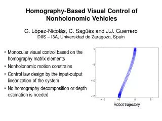
Active Visual ObserverIntegration of Visual Processes for Control of Fixation KTH (Royal Institute of Technology, Stockholm)and Aalborg University C.S. Andersen and H.I.Christensen
Architecture for controlling an agile camera • Basic system facilitates three low level processes: • Fixation • Tracking • Attention selection and shifting
The basic idea • Is that a tight coupling between the lowest visual processes, referred to as the basic system, and the sensing apparatus, with known latencies, is imperative for successful operation in dynamic environments. Following the biological inspiration, the basic functionality of a camera head are: fixation, gaze shift and smooth pursuit. • A system capable of addressing these aspects of active vision will be capable of fixating on an object, and maintaning fixation while it is moving, or during ego motion of the head.
The attention mechanisms • The attention mechanism will allow for selection of interesting (salient?) points from the input data. The system can perform selection of fixation points, fixation and tracking. • Below is a standard control system for a DC motor with tachometer feedback , with “normal” appearance at the top and the control schematic at the bottom.
Designing the Architecture • Biologists have argued convincingly that eye movements typically are performed in two separate stages, Version and vergence, with both eyes participating in both motion patterns, while fixating at some point in the space.The version angle is the direction of gaze for an imaginary eye positioned between the two rotation centers in next figure.
Cyclopean representation The version angle relies on the two vergence motor settings.The pan motor contributes however, along with the vergence motor to the direction of gaze.
Control • We may use one camera as leading and the other following. • The visual process of tracking in the leading eye approach is roughly equivalent to performing control of version and tilt in the cyclopean representation, while fixation corresponds to the process of vergence control. Hence renaming the modules and utilizing a different representation the basic control architecture may facilitate equal eye control as shown in figure below
Notes to the figure • It should be noted that the figure only displays the “forward control lines” . Actually there are feedback signals form the hardware to the visual processes, as well as communication between the individual processing modules. The signals in the system is as described earlier the actions issued by the processing modules, which in this case is vergence,version and tilt angle adjustments. Thus the close connection with the actual control of hardware is still maintained
Completing the Architecture • So far we presented only the mechanical control associated with the eye movements. The system has addiotnal rotational degree of freedom, the pan. There is alos motorized lenses with 3 degrees of freedom: focal length (zoom), focus (accommodation) distance and aperture.
An Experimental System • Final system relies on correlation based stabilization fro the left and right camera. The computed image slip from the two cameras is combined to form the error signal for control of the version and tilt angles. While a disparity estimate could be computed from the target location in the image pair, it has been chosen to perform an explicit disparity extraction by correlating the images. This provides redundant information but it also allows for a more robust control since a loss of disparity information does not necessarily mean that version and tilt control cannot be performed and vice versa.
Fixation distance for combined disparity and accomodation control
Attention selection • The figure below shows how the system selected areas of high contrast. Using the centroid of the receptive field as fixation point, the fixation has been shifted resulting in vergence-version-tilt angle changes as shown to the right of the figure below.
Another Active Visual Observer • Binocular Active Vision System that can attend to and fixate a moving target, in particular is capable of figure-ground segmentation. This work focuses on occlusions of other both stationary and moving targets and integrate three cues to obtain an overall robust behavior, ego-motion, target motion and target disparity.
Major parts of the current system • Selecting a target • Control of the system for saccade and pursuit • Measuring the speed of the target for pursuit • Measuring and selecting a disparity for pursuit
System description • Fundamental skills are: fixation, target pursuit and target discrimination • The full system includes the integration of three cues for target selection and target discrimination. These are used by the moving observer to smoothly pursue moving or stationary targets binocularly while maintaining vergence. Mechanisms for discovering moving targets provide means of attention. There is another mechanism to find and select new locations to attend to.
The system implementation schema (the diamond indicates one frame delay in the feedback)
The Algorithm • Affine Background Motion Model is used for fit. Two steps involving feedback are included to account for object motion and large background motion. • The predicted and previous position and extent of the target is used to mask out parts of the image which likely belong to the object, so that they do not affect the calculation of the affine parameters for the background. • The accumulated parameters are used over time to cancel out the majority of the time difference, see feedback into WARP. • Background segmentation makes a use from the affine calculations
Target segmentation • The aim is to determine which parts of the scene are moving consistently with what is currently believed to be the target. • The calculations on the target are performed in analogy with what is done for the background motion ,i.e. affine model is used.
Disparity selection • The object of disparity selection is to select the disparities that belong to the target in the presence of disparities that arise from other locations in the scene. They are using the disparity histogram ,selecting the highest peak.
Integration • Target areas that do nto get support from either motion detection or taret segmentation are excluded from the target model. Also the disparity module detects areas in the scene that lie in front of the pursuing target, which are then excluded from the target model. • Areas that are detected as both moving independently as detected by motion detection and are moving consistent with the target image velocity model from the target segmentation are added to the target model.
Real time pursuit • Centers a target visually while the target is moving across the room. In the second figure when the target in last row second frame moves behind the occluding object the pursuit does not follow the target,but stays on the occluding object
Figure ground segmentation extracts the target from previous sequence
Motion detection returns areas that possibly belong to moving target
Traget segmentation returns areas that are believed pursued target
Target pixels extracted without disparity cue. Attention shifts to the second moving perosn
Notes • On the top is shown the original sequence during pursuit. • The bottom row shows result of the segmentation every 3d frame