Download
1 / 30
350 likes | 847 Views
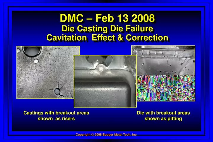
DMC – Feb 13 2008 Die Casting Die Failure Cavitation Effect & Correction. Castings with breakout areas shown as risers. Die with breakout areas shown as pitting. Could this lead to a New Chapter in the study of High Pressure Die failure?.

E N D
DMC – Feb 13 2008Die Casting Die FailureCavitation Effect & Correction Castings with breakout areasshown as risers Die with breakout areasshown as pitting
Could this lead to a New Chapterin the study of High Pressure Die failure?
Correlation to Die Casting Dies? Steel Failure – Hydraulic Machinery • Construction Equipment – Excavators, Crawler Tractors, Loaders • High Impact Machines – Hammers, Crushers, Etc.
Correlation to Die Casting Dies? Steel Failure – Hydraulic Machinery • Steel Failure – Fast Fill Nitrogen Charge AreasPistonCylinders • Cause and CorrectionContamination of steel - UnsuccessfulDesign changes- UnsuccessfulFailure of other related components
Joint Research Program with Caterpillar • High Speed Photography • Special pressure transducers
Failure Mode - Cavitation • Previously mistaken for:Bad steelErosionHeat Treatment • None of the Above Does this look familiar?
What is Cavitation – Really? • Fatigue by Fluid entrained gases • Tiny bubbles imploding on surface of the member on which or over which the fluid is flowing • Resulting in high cycle fatigue failure Image source: Dr. Joe Evans Ph.D www.pumped101.comwww.caltech.edu
Breaking down the BubbleA tiny Jack Hammer Stages 1-3 spherical Stage 4 small depression Depression more toroidalin its 3D shape. Upon implosion, there-entrant micro jetwould form at the bottomof the bubble with itsenergy directed towardsthe solid surface. Vapor bubble in various stages ofcollapse. Solid lines predictedby model.Dotted lines obtainedthrough experiment. Image source: Dr. Joe Evans Ph.D www.pumped101.comwww.caltech.edu
Bubble Stage CollapseBELOW a Solid Boundary 1-18 shows a bubble collapsing At stage 7, small dot at bottom of bubble Grows in size in following stages then appears to penetrate the upper boundary in Stage 14. Stage 18 is just prior to total collapse and shock wave generation. Image source: Dr. Joe Evans Ph.D www.pumped101.comwww.caltech.edu
Cavitation Effect Cavitation patternduring flow Bubbles formed at leftresult in damage at right Source: Dr. Joe Evans Ph.D www.pumped101.comwww.caltech.edu
Where does Cavitation Show Up? • Gear Pump:suction side of pumpnegative pressures at entrypositive pressures at first gear tooth • How to accelerate?Increase air entrainmentcavitation failure was acceleratedcavitation failure more pronounced Photo at right shows damage at lowpressure side of leading edge ofimpeller
Collapsing Bubble Damage • Propellers, Pumps, Cylinders, • High Pressure Die Casting
How do little bubbles do so much damage? • Each operational cycle:millions of low pressure cyclescycles go from void to positive pressuresthousands – translates to billions • Billions of cyclescause extremely high cycle fatigueinitially microscopic particles removedas more removed – visible to naked eye
How about Die Casting Dies? • Fact - Trapped gases in molten metal:collapse - billions of void to positive pressurescause loss of fatigue strength of metalinitially microscopic • Jack hammer effectsmall microscopic particles grow in sizevisible chucks of metal from diepreviously attributed to thermal fatigue
Surface experiences void to positive pressure cycles of trapped gas bubbles Die Steel Cover Insert Metal Flow Die Steel Ejector Insert Bubbles implode on surface as metal flows Die Cast Trapped Gas – Phase 1 More Infoon our web
Effect of billions of low pressure cycles during the implosion of millions of bubbles on the metal Die particles begin to be removed Metal Flow with trapped gas Die surface begins to fatigue At first, as metal weakens, only microscopic particles are removed Die Cast Trapped Gas – Phase 2 More Infoon our web
Then removed particles increase in size as surface fatigues More die particles removed Metal Flow with trapped gas Die break out and/or heat check starts Combined breakout and heat checking evident Visible Break Out & Heat Checking More Infoon our web
Over past 25 Years100,000+ die casting dies In the USA, Canada & Mexico
Historical Evidence • 100,000+ Dies in 25 yearsNo Die Caster, Tool Shop –sees more • Castings tell the bubble storybreakout prevalent at gate area of castingbreakout prevalent at flow direction change • Everyday we see damage caused by cavitationdamage attributed to bad steel, heat treat, erosion
Mistaken Identity • Asked to repair heat checks in diemajority of time these are breakout conditionsNOT HEAT CHECKING • Usually close to gate areacan feel with eyes closed the pittingalso evident in flow change areas
How to Counter Die Cast DieCavitation Effect? • Remove all trapped gases - Impossible • Get rid of bubbles – Break them up • Increase fatigue resistance of steel • Place surface in compression • Increase surface hardness
How does helpreduce cavitation effect? • Breaks up trapped gas bubbles • High compression to counter fatigue • Micro-texture improves flow
As metal flows, compressive texturing dissipates bubbles at die's surface Removes damaging gas bubbles Metal Flow with trapped gas Compressive Textured Surface Breakout problem addressed plus die fatigue strength increased Compressive Texturing Effect
T-41H High Surface Compression Shallow Knee Maximized Depth X-Ray Diffraction Curves High Compressive Values help counter metal fatigue failure Residual Stress Curves
anti-solderingpermanent flow effect TOOLING CYCLE OF LIFE TOOLING CIRCLE OF LIFE “resistance to thermal fatigue cracking & breakout from cavitation effect Badger Metal Tech, Inc.FAX 262-252-3956Toll Free 800-366-1973
Additional Benefits • Reduced cavitation breakout and pitting • Eliminate lamination porosity • Better heat dissipation • Increased lubricity and improved metal flow • Compressive stress after weld repair • Better paint adherence – especially powder Why apparent less porosity?
Gas bubbles trapped between casting layers Die Steel Cover Insert Casting SurfaceLamination with trapped gas Die Steel Ejector Insert Solidified casting exhibits porosity with gas trapped laminations Lamination of Casting Skin
Gas bubbles in molten metal dissipated which eliminates casting layers Die Steel Cover Insert Casting Surface Casting Surface Die Steel Ejector Insert Lamination and porosity problem addressed Problem Solved
To make effect permanent • Where a need exists for an anti-soldering, anti-galling or washout Return to first slide Continue


![Heart Failure [HF]](https://cdn2.slideserve.com/5103874/heart-failure-hf-dt.jpg)