Download
1 / 41
410 likes | 488 Views
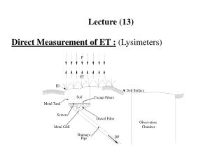
Lecture 13. Memory Subsystem. Introduction. The general-purpose memory controller (GPMC) is an unified memory controller dedicated to interfacing external memory devices The general features of the GPMC module include Data path to external memory device can be 16- or 8-bit wide

E N D
Lecture 13 Memory Subsystem NCHUEE 720A Lab Prof. Jichiang Tsai
Introduction • The general-purpose memory controller (GPMC) is an unified memory controller dedicated to interfacing external memory devices • The general features of the GPMC module include • Data path to external memory device can be 16- or 8-bit wide • 32-bit OCPIP 2.0 compliant core, single slave interface • Up to 100 MHz external memory clock performance • Support for the following memory types • External asynchronous or synchronous 8-bit width memory or device • External asynchronous or synchronous 16-bit width memory / device • External 16-bit non-multiplexed NOR Flash device • External 16-bit address and data multiplexed NOR Flash device • Selected through the GPMC_CONFIG1_i[9-8] MUXADDDATA bit field NCHUEE 720A Lab Prof. Jichiang Tsai
Introduction (cont.) • External 8-bit and 16-bit NAND flash device • External 16-bit pseudo SRAM device • Up to 16-bit ECC support for NAND flash • Using BCH code (t=4, 8 or 16) or Hamming code for 8-bit or 16-bit NAND-flash, organized with page size of 512 bytes, 1K bytes, or more • Support 512M Bytes maximum addressing capability • Can be divided into seven independent chip-select • With programmable bank size and base address on 16M Bytes, 32M Bytes, 64M Bytes, or 128M Bytes boundary • Fully pipelined operation for optimal memory bandwidth usage • Support external device clock frequency of 1, 2, 3 and 4 divider from L3 clock • Support programmable auto-clock gating when no access • Support Midlereq/SidleAck protocol NCHUEE 720A Lab Prof. Jichiang Tsai
Introduction (cont.) • Support the following interface protocols when communicating with external memory or external devices • Asynchronous read/write access • Asynchronous read page access (4-8-16 Word16) • Synchronous read/write access • Synchronous read burst access without wrap capability (4-8-16 Word16) • Synchronous read burst access with wrap capability (4-8-16 Word16) • Address and Data multiplexed access • Each chip-select as independent and programmable control signal timing parameters for Setup and Hold time • Parameters are set according to the memory device timing parameters, with one L3 clock cycle timing granularity NCHUEE 720A Lab Prof. Jichiang Tsai
Introduction (cont.) • Flexible internal access time control (wait state) and flexible handshake mode using external WAIT pins monitoring • Up to two WAIT pins • Support bus keeping • Support bus turn around • Pre-fetch and write posting engine associated with system DMA to get full performance from NAND device • With minimum impact on NOR/SRAM concurrent access • On the fly ECC Hamming Code calculation to improve NAND usage reliability with minimum impact on SW • GPMC can access various external devices through the L3 Slow Interconnect NCHUEE 720A Lab Prof. Jichiang Tsai
Introduction (cont.) • The flexible programming model allows a wide range of attached device types and access schemes • Based on the programmed configuration bit fields in the GPMC registers, GPMC is able to generate all control signals timing • Given the chip-select decoding and its associated configuration registers, it selects the appropriate device type control signals timing • The GPMC consists of six blocks • Interconnect port interface • Address decoder, GPMC configuration, and chip-select configuration register file • Access engine & Prefetch and write-posting engine • Error correction code engine (ECC) • External device/memory port interface NCHUEE 720A Lab Prof. Jichiang Tsai
GPMC Block Diagram NCHUEE 720A Lab Prof. Jichiang Tsai
Integration NCHUEE 720A Lab Prof. Jichiang Tsai
Connectivity Attributes & Clock and Reset Management • The GPMC is a synchronous design and operates from the same clock as the Slow L3 • All timings use this clock as a reference NCHUEE 720A Lab Prof. Jichiang Tsai
Pin List • The GPMC does not drive unnecessary address lines • They stay at their reset value of 00 NCHUEE 720A Lab Prof. Jichiang Tsai
GPMC Modes • GPMC to 16-Bit Address/Data-Multiplexed Memory NCHUEE 720A Lab Prof. Jichiang Tsai
GPMC Modes (cont.) • GPMC to 16-Bit Non-multiplexed Memory NCHUEE 720A Lab Prof. Jichiang Tsai
GPMC Modes (cont.) • GPMC to 8-Bit NAND Device NCHUEE 720A Lab Prof. Jichiang Tsai
GPMC Functional Description • Offers maximum flexibility to support various access protocols for each of eight configurable chip-selects • Based on the characteristics of the external device • Different protocols can be selected to support generic asynchronous or synchronous random-access devices (NOR flash, SRAM) or to support specific NAND devices • The address and the data bus can be multiplexed on the same external bus • Read and write access can be independently defined as asynchronous or synchronous • System requests (byte, 16-bit word, burst) are performed through single or multiple accesses • External access profiles (single, multiple with optimized burst length) are based on external device characteristics (supported protocol, bus width, data buffer size) NCHUEE 720A Lab Prof. Jichiang Tsai
GPMC Functional Description (cont.) • System burst read or write requests are synchronous-burst (multiple-read or multiple-write) • When neither burst nor page mode is supported by external memory, system burst read or write requests are translated to successive single synchronous or asynchronous accesses (single reads or single writes) • 8-bit wide devices are supported only in single synchronous or single asynchronous read or write mode • To simulate a programmable internal-wait state, an external wait pin can be monitored to dynamically control external access at the beginning (initial access time) and during a burst access • Each control signal is controlled independently for each CS • The internal functional clock of the GPMC (GPMC_FCLK) is used as a time reference to specify the following • Read- and write-access duration • Data-capture time during read access NCHUEE 720A Lab Prof. Jichiang Tsai
GPMC Functional Description (cont.) • Most GPMC external interface control-signal assertion and deassertion times • External wait-pin monitoring time • Duration of idle time between accesses, when required • The GPMC_CLK is generated by the GPMC from the internal GPMC_FCLK clock • External clock provided to synchronous external memory devices • The GPMC_CLK is configured via the GPMC_CONFIG1_i[1-0] GPMCFCLKDIVIDER field (for i = 0 to 3) NCHUEE 720A Lab Prof. Jichiang Tsai
GPMC Software Reset • The GPMC can be reset by software • Through the GPMC_SYSCONFIG[1] SOFTRESET bit • Setting the bit to 1 enables an active software reset functionally equivalent to a hardware reset • Hardware and software resets initialize all GPMC registers and the finite state-machine (FSM) immediately and unconditionally • The GPMC_SYSSTATUS[0] RESETDONE bit indicates that the software reset is complete when its value is 1 • The software must ensure that the software reset completes before doing GPMC operations • GPMC power management complies with system power-management guidelines • GPMC power is supplied by the CORE power domain • Clock Auto Gating and Slave Idle Modes NCHUEE 720A Lab Prof. Jichiang Tsai
GPMC Interrupt Requests • The GPMC generates one interrupt event • The interrupt request goes from GPMC (GPMC_IRQ) to the Cortex-A8 MPU subsystem: A_IRQ_100 • The GPMC generates one DMA event • From GPMC (GPMC_DMA_REQ) to the eDMA: e_DMA_53 NCHUEE 720A Lab Prof. Jichiang Tsai
GPMC Address and Data Bus • Supports GPMC connection to NAND devices and to address/data-multiplexed memories or devices • Connection to address/data-nonmultiplexedmemories depending on the GPMC configuration of each chip-select • Address and data bus lines that are not required for a particular access protocol are not updated (changed from current value) and are not sampled when input (input data bus) • The GPMC L3 Slow interconnect interface is a pipelined interface including an 16 × 32-bit word write buffer • Any system host can issue external access requests through the GPMC NCHUEE 720A Lab Prof. Jichiang Tsai
Address Decoder and Chip-Select Configuration • Addresses are decoded accordingly with • The address request of the chip-select and the content of the chip-select base address register file • Includes a set of global GPMC configuration registers and eight sets of chip-select configuration registers • The GPMC configuration register file is memory-mapped • Can be read or written with byte, 16-bit word, or 32-bit word • Should be configured as a noncacheable, nonbufferable region • After the chip-select is configured • The access engine accesses the external device, drives the external interface control signals, and applies the interface protocol based on user-defined timing parameters and settings NCHUEE 720A Lab Prof. Jichiang Tsai
Chip-Select Base Address and Region Size • Any external memory or ASIC device attached to the GPMC external interface can be accessed • By any device system host within the GPMC 512-Mbyte contiguous address space • The GPMC 512 Mbyte address space can be divided into a maximum of seven chip-select regions • With programmable base address and programmable CS size • The CS size is programmable from 16 Mbytes to 256 Mbytes • Must be a power-of-2 and defined by the mask field • Attached memory smaller than the programmed CS region size is accessed through the entire CS region (aliasing) • Each chip-select has a 6-bit base address encoding and a 4-bit decoding mask NCHUEE 720A Lab Prof. Jichiang Tsai
Chip-Select Base Address and Region Size (cont.) • The programmed chip-select region base address must be aligned on the chip-select region size address boundary • Limited to a power-of-2 address value • During access decoding, the register base address value is used for address comparison with the address-bit line mapping • Base address is programmed through the GPMC_CONFIG7_i[5-0] BASEADDRESS bit field • The register mask is used to exclude some address lines from the decoding • A register mask bit field cleared to 0 suppresses the associated address line from the address comparison • Incoming address bit line is don't care • The register mask value must be limited to the subsequent value, based on the desired chip-select region size • Any other value has an undefined result NCHUEE 720A Lab Prof. Jichiang Tsai
Chip-Select Base Address and Region Size (cont.) • When multiple chip-select regions with overlapping addresses are enabled concurrently, access to these chip-select regions is cancelled • An error is generated and no access will occur on either chip-select • The mask field is programmed through the GPMC_CONFIG7_i[11-8] MASKADDRESS bit field • Chip-select configuration (base and mask address or any protocol and timing settings) must be performed • While the associated chip-select is disabled • Through the GPMC_CONFIG7_i[6] CSVALID bit • A chip-select configuration can only be disabled if there is no ongoing access to that chip-select • Requires activity monitoring of the prefetch or write-posting engine if the engine is active on the chip-select • The write buffer state must be monitored to wait for any posted write completion NCHUEE 720A Lab Prof. Jichiang Tsai
Chip-Select Base Address and Region Size (cont.) • Any access attempted to a nonvalid GPMC address region is not propagated to the external interface • CSVALID disabled or address decoding outside a valid chip-select region • A GPMC access error is posted • Chip-select 0 is the only chip-select region enabled after either a power-up or a GPMC reset • The GPMC interface can drive up to seven chip-selects • The frequency specified for this interface is for a specific load • If this load is exceeded, the maximum frequency cannot be reached • One solution is to implement a board with buffers • To allow the slowest device to maintain the total load on the lines NCHUEE 720A Lab Prof. Jichiang Tsai
Chip-Select Address Mapping and Decoding Mask NCHUEE 720A Lab Prof. Jichiang Tsai
Access Protocol • The access protocol of each chip-select can be independently specified • Via the GPMC_CONFIG1_i[11-10] DEVICETYPE parameter • Random-access synchronous or asynchronous memory like NOR flash, SRAM • NAND flash asynchronous devices • Each chip-select can be independently configured through the GPMC_CONFIG1_i[13-12] DEVICESIZE field • To interface with a 16-bit wide device or an 8-bit wide device • System requests with data width greater than the external device data bus width are split into successive accesses • According to both the external device data-bus width and little-endian data organization NCHUEE 720A Lab Prof. Jichiang Tsai
Access Protocol (cont.) • An 8-bit wide device must be interfaced to the D0-D7 external interface bus lane • GPMC data accesses only use this bus lane when the associated chip-select is attached to an 8-bit wide device • The 8-bit wide device can be interfaced in asynchronous or synchronous mode in single data phase • No 8-bit wide device burst mode • ReadMultipleand WriteMultiple bit fields are considered “don’t care” and only single accesses are performed • A 16-bit wide device can be interfaced in asynchronous or synchronous mode, with single or multiple data phases • For random synchronous or asynchronous memory interfacing (DEVICETYPE = 0b00) NCHUEE 720A Lab Prof. Jichiang Tsai
Access Protocol (cont.) • An address- and data-multiplexing protocol can be selected • Through the GPMC_CONFIG1_i[[9-8] MUXADDDATA bit field • The ADVn signal must be used as the external device address latch control signal • ADVnassertion and deassertion time and OEn assertion time must be set to the appropriate value • To meet the address latch setup/hold time requirements of the external device • This address/data-multiplexing interface is not applicable to NAND device interfacing • NAND devices require a specific address, command, and data multiplexing protocol NCHUEE 720A Lab Prof. Jichiang Tsai
External Signals • GPMC access time can be dynamically controlled • Using an external gpmc_waitpin • When the external device access time is not deterministic • Cannot be defined and controlled only using the GPMC internal RDACCESSTIME, WRACCESSTIME and PAGEBURSTACCESSTIME wait state generator • The GPMC features two input wait pin • gpmc_wait1, and gpmc_wait0 • Allow control of external devices with different wait-pin polarity • Allow the overlap of wait-pin assertion from different devices • Without affecting access to devices for which the wait pin is not asserted • The GPMC_CONFIG1_i[17-16] WAITPINSELECT bit field (where i = 0 to 6) selects which input gpmc_waitpin is used for the device attached to the corresponding chip-select NCHUEE 720A Lab Prof. Jichiang Tsai
External Signals (cont.) • The polarity of the wait pin is defined through the WAITxPINPOLARITY bit of the GPMC_CONFIG register • A wait pin configured to be active low means that low level on the WAIT signal indicates that the data is not ready and that the data bus is invalid • When WAIT is inactive, data is valid • The GPMC access engine can be configured per CS to monitor the wait pin of the external memory device or not • The GPMC_CONFIG1_i[22] WAITREADMONITORING bit defines if the wait pin should be monitored during read accesses or not • The GPMC_CONFIG1_i[21] WAITWRITEMONITORING bit defines if the wait pin should be monitored during write accesses or not • The engine can be configured to monitor the wait pin asynchronously or synchronously with the GPMC_CLK clock • Depending on the access type: synchronous or asynchronous • The GPMC_CONFIG1_i[29] READTYPE and [27] WRITETYPE bits NCHUEE 720A Lab Prof. Jichiang Tsai
Wait Behavior During an Asynchronous Single Read Access NCHUEE 720A Lab Prof. Jichiang Tsai
Wait Behavior During a Synchronous Read Burst Access NCHUEE 720A Lab Prof. Jichiang Tsai
Bus Turnaround • To prevent data-bus contention, an access that follows a read access to a slow memory/device must be delayed • The bus turnaround is a time-out counter starting after CSn or OEn de-assertion time • To delays the next access start-cycle time • Programmed through the GPMC_CONFIG6_i[3-0] BUSTURNAROUND bit field • After a read access to a chip-select with a non zero BUSTURNAROUND, the next access is delayed • Until the BUSTURNAROUND delay completes • Bus keeping starts after bus turnaround completion • DIR changes from IN to OUT after bus turnaround NCHUEE 720A Lab Prof. Jichiang Tsai
Read to Read / Write for an Address-Data Multiplexed Device NCHUEE 720A Lab Prof. Jichiang Tsai
NOR Access Description • Asynchronous and synchronous read and write access time and related control signals are controlled • Through timing parameters that refer to GPMC_FCLK • The primary difference of synchronous mode is • The availability of a configurable clock interface (GPMC_CLK) to control the external device • In asynchronous operations GPMC_CLK is not provided outside the GPMC and is kept low • Synchronous mode also affects data-capture and wait-pin monitoring schemes in read access • The address bus and BE[1:0]n are fixed for the duration of a synchronous burst read access • They are updated for each beat of an asynchronous page-read access NCHUEE 720A Lab Prof. Jichiang Tsai
Asynchronous Single Read Operation on an Address/Data Multiplexed Device NCHUEE 720A Lab Prof. Jichiang Tsai
Asynchronous Single Write on an Address/Data-Multiplexed Device NCHUEE 720A Lab Prof. Jichiang Tsai
Synchronous Single Read (GPMCFCLKDIVIDER = 1) NCHUEE 720A Lab Prof. Jichiang Tsai
Synchronous Multiple (Burst) Read (GPMCFCLKDIVIDER = 0) NCHUEE 720A Lab Prof. Jichiang Tsai
Synchronous Single Write on an Address/Data-Multiplexed Device NCHUEE 720A Lab Prof. Jichiang Tsai
Synchronous Multiple Write in Address/Data-Multiplexed Mode NCHUEE 720A Lab Prof. Jichiang Tsai