Download
1 / 50
520 likes | 797 Views
Chapter 5A EGR 270 – Fundamentals of Computer Engineering. 1. Reading Assignment: - Chapter 5 in Logic and Computer Design Fundamentals, 4 th Edition by Mano - Online supplement to text “Design and Analysis using JK and T Flip-Flops” (www.prenhall.com/mano).

E N D
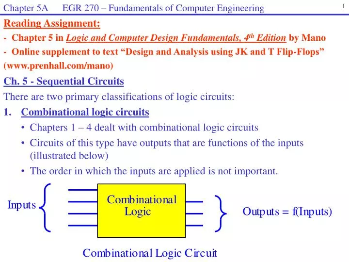
Chapter 5A EGR 270 – Fundamentals of Computer Engineering 1 Reading Assignment: - Chapter 5 in Logic and Computer Design Fundamentals, 4th Edition by Mano - Online supplement to text “Design and Analysis using JK and T Flip-Flops” (www.prenhall.com/mano) • Ch. 5 - Sequential Circuits • There are two primary classifications of logic circuits: • 1. Combinational logic circuits • Chapters 1 – 4 dealt with combinational logic circuits • Circuits of this type have outputs that are functions of the inputs (illustrated below) • The order in which the inputs are applied is not important.
Chapter 5A EGR 270 – Fundamentals of Computer Engineering 2 • 2. Sequential logic circuits • Chapter 5 introduces sequential logic circuits • Circuits of this type have outputs that are functions of both inputs and previous outputs (illustrated below) • Sequential circuits contain some type of memory elements. As an example, a counter must “remember” that its previous output was 6 in order to produce its new output 7. • Sequential logic circuits typically also include some combinational logic components. Inputs Combinational Outputs = f(inputs + past outputs) Logic Memory Sequential Logic Circuit
Chapter 5A EGR 270 – Fundamentals of Computer Engineering 3 • There are two main types of sequential circuits: • 1) Synchronous Sequential Circuits (also called Clock Sequential Circuits) • All signals are synchronized to some “master clock” • The memory devices respond only when activated by the master clock • The most common memory device: the flip-flop • This course will primarily focus on this type of sequential circuit • Circuits can be designed using systematic methods such as: • Excitation table method • State equation method • One-hot method • 2) Asynchronous Sequential Circuits • Outputs depend solely on the order in which the inputs change, so timing is critical. • The design methods used for synchronous sequential circuits do not apply to asynchronous circuits. As a result, design is difficult and is perhaps covered in more advanced courses.
Chapter 5A EGR 270 – Fundamentals of Computer Engineering 4 S Q S Q Clock input R Q’ R Q’ SR Latch SR Flip-Flop • Flip-flops and latches • Binary memory cell capable of storing 1 bit of information (0 or 1) • Have two outputs, Q and Q’ • Q = binary state = present state = value stored • Maintain the present state Q indefinitely until inputs instruct it to change • Flip-flops and latches behave as described above but have one key difference: • A latch can change states whenever the input signals change • A flip-flop has a clocked input and can only change at certain times specified by the type of clocking. So a flip-flop could be called a clocked latch. See below.
Chapter 5A EGR 270 – Fundamentals of Computer Engineering 5 Basic RS (or SR) Latch Operation A simple SR latch can be constructed using either two NAND gates or two NOR gates with feedback connections. The NOR circuit is shown below. Determine the truth table for the RS latch shown by analyzing the circuit for various cases: Case 1: S = 1, R = 0 (Set) Case 2: S = 0, R = 1 (Reset)
Chapter 5A EGR 270 – Fundamentals of Computer Engineering 6 Case 3: S = 0, R = 0 (No Change) A) Latch originally Reset B) Latch originally Set Case 4: S = 1, R = 1 (Illegal) Summary: Truth Table for SR Latch
Chapter 5A EGR 270 – Fundamentals of Computer Engineering 7 SR Flip-flop A flip-flop is essentially a clocked latch. In other words, a flip-flop is a latch that is only allowed to change during certain portions of the clock cycle. Adding AND gates to the SR latch below results in a latch that can only change when Clock = 1. Discuss the operation of the simple clocked RS latch shown below. Hint: Find the values of R1 and S1 when Clock = 0 and when Clock = 1 R1 R Q Clock Q S S1
Chapter 5A EGR 270 – Fundamentals of Computer Engineering 8 • Flip – flops - There are 4 primary types of flip-flops: • SR flip-flop • D flip-flop • JK flip-flop • T flip-flop For each type of flip-flop, show the truth table and symbol.
Chapter 5A EGR 270 – Fundamentals of Computer Engineering 9 • Relationship between different types of flip – flops • Show how to create a D flip-flop from an SR flip-flop or a JK flip-flop • Show how to create a T flip-flop from a JK flip-flop
Chapter 5A EGR 270 – Fundamentals of Computer Engineering 10 • When are each type of flip-flop used? • JK and D flip-flops will be most commonly used in this course. • JK flip-flops are the most powerful and yield the simplest sequential circuits • D flip-flops are easiest to design with and are commonly used with programmable devices (PLDs and FPGAs) • SR flip-flops are the simple to introduce using NOR gate circuits • T flip-flops are sometimes used design simple counters by noting when certain bits toggle.
Chapter 5A EGR 270 – Fundamentals of Computer Engineering 11 Triggering of flip-flops A trigger is a momentary change in the input clock signal which allows for a possible change in the state of the flip-flop. Flip-flops are typically triggered by pulse transitions, using either the rising (positive) edge or the falling (negative) edge of the clock waveform (see below).
Chapter 5A EGR 270 – Fundamentals of Computer Engineering 12 • There are 3 common types of triggering: • 1. Positive-edge triggering – the flip-flop output can only change on the positive edges of the clock • 2. Negative-edge triggering – the flip-flop output can only change on the negative edges of the clock • Master-slave– Internally this flip-flop is constructed using two flip-flops called the master and the slave. The master flip-flop “reads” the input values on the positive edge of the clock, and the output Q of the master is transferred to the slave on the negative clock edge. • The following symbols are sometimes used to indicate the type of triggering. J Q J Q J Q Clock Clock C Clock K Q K Q K Q Positive-edge triggered JK flip-flop Negative-edge triggered JK flip-flop Master-slave JK flip-flop -
Chapter 5A EGR 270 – Fundamentals of Computer Engineering 13 Master-slave- Discuss how the master-slave flip-flop below works. Master Slave Q J1 J2 Q2 J Q1 Clock Q Q2 Q1 K1 K2 K
Chapter 5A EGR 270 – Fundamentals of Computer Engineering 14 • Example: Given J, K, and Clock input waveforms, sketch the output Q for a JK flip-flop if each flip-flop is initially LOW and the type of triggering is: • a) positive-edge triggering (labeled as Q1) • b) negative-edge triggering (labeled as Q2) • master-slave triggering (labeled as Q3) Clock J K Q1 Q2 Q3
Chapter 5A EGR 270 – Fundamentals of Computer Engineering 15 • Asynchronous (Direct) Inputs • Two inputs are commonly available that can be used to initialize a flip-flop independently of the clock: • PRESET – used to initialize the flip-flop to Q = 1 • CLEAR – used to initialize the flip-flop to Q = 0 • Sketch a JK flip-flop with active-LOW inputs for PRESET and CLEAR.
Chapter 5A EGR 270 – Fundamentals of Computer Engineering 16 Clock J K PR CLR Q Example: Given J, K, PRESET, CLEAR and Clock input waveforms for a negative-edge triggered JK flip-flop, sketch Q. Assume that PRESET and CLEAR are active-LOW inputs.
Chapter 5A EGR 270 – Fundamentals of Computer Engineering 17 • Commercially available flip-flop IC’s. A few are listed below and PSPICE • symbols are shown below also. • 7473 Dual JK Master-Slave (pulse-triggered) Flip-flop with CLEAR • 7473A Dual JK Negative-Edge Triggered Flip-flop with CLEAR • 7474 Dual D Positive-Edge Triggered Flip-flop with PRESET and CLEAR • 7476B Dual JK Master-Slave Flip-flop with PRESET and CLEAR • 74109 Dual D Positive-Edge Triggered Flip-flop with PRESET and CLEAR • 74111 Dual JK Master-Slave Flip-flop with PRESET and CLEAR • 74279 Quadruple S’-R’ Latch
Chapter 5A EGR 270 – Fundamentals of Computer Engineering 18 • Synchronous Logic Circuits versus Combinational Logic Circuits • Let’s begin by comparing how we describe each type of circuit. • Descriptions of Combinational Logic Circuits • Recall that there are numerous ways to describe a combinational logic circuit, including: • Truth tables • Karnaugh maps • (minterms) • (maxterms) • Boolean expressions • SOP expressions • POS expressions • Logic diagrams • VHDL descriptions • Note: Given any one of the descriptions above, we could determine all of the others.
Chapter 5A EGR 270 – Fundamentals of Computer Engineering 19 • Descriptions of Sequential Logic Circuits • Similarly, there are numerous ways to describe a sequential logic circuit, including: • State diagrams • State tables • State equations and output equations • Input equations (flip-flop input functions) and output equations • Logic diagrams • VHDL descriptions • Note: Given any one of the descriptions above, we could determine all of the others. • Some of these ways to describe sequential circuits will now be introduced. Finite State Machines (FSM)– Sequential circuits are also referred to as finite state machines. The circuit operates by moving between a finite number of pre-determined states.
Chapter 5A EGR 270 – Fundamentals of Computer Engineering 20 State Diagrams This is the most common way to describe a sequential circuit. A state diagram is somewhat like a flowchart that describes the sequence to states through which the circuit might progress. State – a distinct event that is to occur (one event in a sequence) Example: A state might be a single count in a counter. If a counter counts 0, 1, 2, ….. , 9 and then repeats, then it has 10 unique states. If four flip-flops were used to store the count, then the flip-flops would store the values 1001 corresponding to state 9. Example: A state might be one step in a machining operation (there might be 5 states corresponding to the operations drill, ream, counterbore, countersink, and polish). Example: A traffic light controller might have three states: Green, Yellow, and Red. Under certain input conditions or at certain times, the controller will change state.
Chapter 5A EGR 270 – Fundamentals of Computer Engineering 21 Encoding states – Show how a binary code can be stored in a set of flip-flops. In most cases, Number of flip-flops needed = log2(Number of states) Example: Determine the number of states needed in each case below:
Chapter 5A EGR 270 – Fundamentals of Computer Engineering 22 X X/Y A/Y B/Y A B Mealy Model • Transition from one state to another depends on the Input, X • Output, Y, is specified with the transition • Output, Y, depends on both the Present State and the Input, X There are two primary types of state diagrams (state machines): Mealy state machine (Mealy model)– the output depends on the present state and the inputs applied. Moore state machine (Moore model)– the output only depends on the present state. We will primarily use Mealy models X X/Y C/Y C Moore Model • Transition from one state to another depends on the Input, X • Output, Y, is specified with the Present State • Output, Y, depends only on the Present State
Chapter 5A EGR 270 – Fundamentals of Computer Engineering 23 Examples of state diagrams: A) Modulo-5 (mod-5) counter: B) 3-bit Up/Down counter: C) Traffic Light Controller
Chapter 5A EGR 270 – Fundamentals of Computer Engineering 24 0/0 1/0 1/0 A 0/1 D B 1/1 C 0/0 1/0 0/1 State Table- A state table provides the same information as the state diagram, but in tabular form. Example: Determine the state table for the state diagram shown below. Is this a Mealy machine or a Moore machine?
Chapter 5A EGR 270 – Fundamentals of Computer Engineering 25 State Assignment Some state diagrams have states indicated by letters or names because there is no numeric value assigned to the states. As an example, there are no natural numeric values for the states in a circuit that controls a traffic light (states, RED, YELLOW, and GREEN). In such cases, numeric values must be assigned to each state. In the case of the traffic light, 2 bits are needed to encode the three states, but various possible codes could be used. For example, RED = 00, YELLOW = 01, and GREEN = 10. There are many other possible state assignments. Which is the best assignment to use? We don’t know. This is a current research topic. Example: List possible state assignments for the last problem and repeat the state table using one of the state assignments.
Chapter 5A EGR 270 – Fundamentals of Computer Engineering 26 • Determining the State Diagram from a Logic Diagram • The state table (or state diagram) can be found from the logic diagram using JK (or other types) flip-flops as follows: • Form a table similar to the one on the following slide • List all possible present states • Read expressions for each J and K input from the logic diagram and use these expressions to complete the columns for each J and K (based on present states) • Use the truth table for the JK flip-flop to determine the next state for each present state and the corresponding values of J and K • Read expressions for any outputs from the logic diagram and add them to the table (based on present states) Truth Table for JK Flip-Flop
Chapter 5A EGR 270 – Fundamentals of Computer Engineering 27 Example: Determine the state diagram for the logic diagram shown below.
Chapter 5A EGR 270 – Fundamentals of Computer Engineering 28 Example(continued): Draw the state diagram for the logic diagram on the previous slide.
Chapter 5A EGR 270 – Fundamentals of Computer Engineering 29 • Sequential Circuit Design Methods • Three specific methods will be covered for designing synchronous sequential circuits: • The Excitation Table method • The State Equation method • “One-Hot” method • Excitation Table Method (also read the Online supplement to text “Design and Analysis using JK and T Flip-Flops” available at www.prenhall.com/mano • Before covering the excitation table method, it is useful to develop • the excitation tables for each type of flip-flop.
Chapter 5A EGR 270 – Fundamentals of Computer Engineering 30 Flip-flop Excitation Tables Truth table – defines the output state based on the inputs Excitation table – defines required inputs to cause a transition from one state to another. Example – Complete the excitation table below for the JK flip-flop
Chapter 5A EGR 270 – Fundamentals of Computer Engineering 31 Flip-flop Excitation Tables Excitation tables could similarly be found for SR, D, and T flip-flops. The excitation tables for all 4 types of flip flops have been summarized below.
Chapter 5A EGR 270 – Fundamentals of Computer Engineering 32 • Excitation table method – Design Procedure • Problem description. • Obtain the state table. • Use state assignment to assign binary values to each state if they are symbolic. • Determine the number of flip-flops required and assign a letter or number to each. • Determine the type of flip-flop to use (SR, JK, D, or T). • Derive the circuit excitation table and output table from the state table. • Simplify • a) the circuit output functions • b) the flip-flop input functions • Draw the logic diagram.
Chapter 5A EGR 270 – Fundamentals of Computer Engineering 33 Example: Design a modulo-7 counter (counts 0 to 6 and repeats) using the excitation table method and JK flip-flops. Treat unused counts as “don’t cares.” Flip-flop Excitation Tables Circuit Excitation Table
Chapter 5A EGR 270 – Fundamentals of Computer Engineering 34 Example: (continued) Fill out the K-maps from the excitation table to determine expressions for each J and K input and for each output Flip-flop Input Functions and Circuit Output Functions
Chapter 5A EGR 270 – Fundamentals of Computer Engineering 35 Example: (continued) Draw the logic diagram
Chapter 5A EGR 270 – Fundamentals of Computer Engineering 36 • Example: Use the excitation table method to design a counter as follows: • Treat unused states as “don’t cares” • Use JK flip-flops • Include an input switch, x, such that the counter operates as follows: • If x = 0: Counts 1, 2, 3, 4, 5 and repeats • If x = 1: Counts 5, 4, 3, 2, 1 and repeats • A) Draw the state diagram
Chapter 5A EGR 270 – Fundamentals of Computer Engineering 37 • B) Fill out the excitation table Flip-flop Excitation Tables Circuit Excitation Table
Chapter 5A EGR 270 – Fundamentals of Computer Engineering 38 • C) Fill out the K-maps to determine the J and K inputs Flip-flop Input Functions and Circuit Output Functions
Chapter 5A EGR 270 – Fundamentals of Computer Engineering 39 • D) Draw the logic diagram
Chapter 5A EGR 270 – Fundamentals of Computer Engineering • Counters • Counters are an important class of sequential circuits. • A counter changes state upon application of an input pulse. The input pulse is not necessarily a periodic clock. For example, a traffic counter is “clocked” each time a car passes. • Key uses of counters • Count occurrences of an event • Examples: • Traffic counter • Line counter on ASEE autonomous vehicle (illustrate in class) • Wheel revolution counter • Generate timing sequences to control operations • Example: Use a mod-16 counter to control a traffic light (Green for 8 counts, Yellow for 1 count, and Red for 7 counts). More details later. • Frequency division – Use a “master “clock generator to create the highest frequency and then create lower frequencies by dividing the master clock.
Chapter 5A EGR 270 – Fundamentals of Computer Engineering Example: Show that a JK flip-flop in the toggle mode acts as a modulo-2 counter or a divide-by-2 circuit.
Chapter 5A EGR 270 – Fundamentals of Computer Engineering Example: Show that a 3-bit counter can serve as a modulo-8 counter or a divide-by-8 circuit.
Chapter 5A EGR 270 – Fundamentals of Computer Engineering Example: The circuit below has a 1MHz master clock and uses counters (as frequency dividers) to provide synchronized lower frequencies. Determine the frequencies f1, f2, and f3. 1 MHz Master Clock (MSB)A B C D f2 Answers: f1 = _______ f2 = _______ f3 = _______ (MSB)A f3 4-bit Counter f1 1 J Q K Q’ 1 J Q K Q’ Divide-by-100 Circuit 1 1 Note: This same technique can be used in software. In Lab 7 we will use a VHDL program that implements a “divide-by-50 million” circuit to produce a 1 Hz clock from the 50 MHz internal clock on an FPGA board. We will need the 1 Hz clock to display a designed counting sequence on a 7-segment display.
Chapter 5A EGR 270 – Fundamentals of Computer Engineering Counters with multiple counting sequences So far we have seen counters with single counting sequences and with 2 counting sequences (controlled by an input switch x). Additional input switches allows for more counting sequences. Example: Design a counter with 2 input switches, x and y, that can count in 4 possible sequences based on the switch positions. Use JK flip-flops.
Chapter 5A EGR 270 – Fundamentals of Computer Engineering Example: (continued) A) Draw the state diagram B) Complete the state table below State diagram State table
Chapter 5A EGR 270 – Fundamentals of Computer Engineering Example: (continued) C) Fill out the excitation table Flip-flop Excitation Tables Circuit Excitation Table
Chapter 5A EGR 270 – Fundamentals of Computer Engineering Example: (continued) Fill out the K-maps to find the flip-flop input functions Draw the logic diagram Logic diagram Flip-flop Input Functions
Chapter 5A EGR 270 – Fundamentals of Computer Engineering Self-starting counters Counters are considered to be self-starting if all unused counts eventually lead to the correct counting sequence. Since the initial state for a flip-flop is unpredictable upon powering up the IC, a counter that is not self-starting could possibly power up into an unused state that would not eventually go into the correct counting sequence (so the counter might “lock up” in an incorrect count or counting pattern. Recall that the next states for unused counts were sometimes treated as “don’t cares.” With this method it is difficult to predict what will happen if the counter powers up into an unused count (although it can be later determined by analyzing the circuit). A safer technique it to let all unused counts have a valid count for their next state.
Chapter 5A EGR 270 – Fundamentals of Computer Engineering 6 7 5 6 7 5 0 0 4 1 4 1 2 3 2 3 Example: Consider the state diagrams for two modulo-5 counters below. Are they self-starting? Case 1: Counter is NOT self-starting. Next states for unused counts 5, 6, and 7 were perhaps treated as don’t cares. Case 2: Counter is self-starting. Next states for unused counts 5, 6, and 7 were all set to count 0.
Chapter 5A EGR 270 – Fundamentals of Computer Engineering Example:Determine the counting sequence for the counter shown (begin with count 0). Use a timing diagram to display the values of Clock, JA, KA, JB, KB, JC, KC, A, B, and C. Is the counter self-starting? Also draw the state diagram. Clock JA KA JB KB C JC KC A B C Count 0