Download
1 / 28
290 likes | 445 Views
Flow injection analysis realized using PCBs S. Gassmann, L. Pagel Faculty of computer since and electronics Institute of Electronic Appliances and Circuits, University of Rostock, Rostock, Germany. Micro fluidics in PCB technology. University of Rostock PCB-Fluidics. Fluidic PCB-Technology.

E N D
Flow injection analysis realized using PCBsS. Gassmann, L. PagelFaculty of computer since and electronicsInstitute of Electronic Appliances and Circuits, University of Rostock, Rostock, Germany
Fluidic PCB-Technology normal PCB production • drilling • milling
Fluidic PCB-Technology normal PCB production • etching
Fluidic PCB-Technology • second PCB stacked • copper lines build channels • gluing
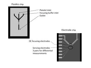
Fluidic PCB-Technology tube connection channel view
Fluidic PCB-Technology cross section of channel
Cross section of channel wall epoxy copper (2) copper (1) channel
µC controlled programmable micro pump • Electrical connector • Power 4 –7 V DC • I2C - Bus • programming • 500µl/min Flow • 150 mBar max Backpressure • over USB-I2C IF fully programmable
Flow-Injection-Analysis • quantitative measurement of components • automated procedure • short response times / high sample throughput • usage in quality control / automated assays • developed by J. Růžička and E.H. Hansen in the year 1975
Flow-Injection-Analysis Sample Reagent Injection valve Detector Pump Reaction coil
Reaction • Detection of Fe3+ • Thiocyanate as reagent • forms red colored Iron-Thiocyanate • detection by absorption at 480 nm
Why a FIA? • All basic fluidic handling necessary - transportation of fluids - dosing of fluids - mixing - detecting - adoption to detection needed - electronics needed
FIA in PCB-Technologie Principle injection detector reagent pump photometrical 480 nm reaction coil sample pump • 2 separate controllable pumps • no injection valve • optical detection
MIXING Flow pattern in 180° curves
Simulation results of the used reaction channel Parameters: 2 pumps with constant flow of 0.2ml/min Fluidsimulation: FLOWORKS 789388 cells
Simulation results of the used reaction channel parameters: thermopneumatically actuated pumps with pulsing flow of 0.2ml/min, 789388 cells
Simulation results of the reaction channel vector plot of the fluid velocity at the cross section of the channel after the second curve parameters: thermopneumatically actuated pumps with pulsing flow of 0.2ml/min, 789388 cells
Realization • stack of four PCBs • one movable layer • of polyimid • electronics on the back • of the fourth PCB 5 cm 5 cm
Signals in the photo detector in dependence on the concentration of Fe(III)ions
PCB FIA facts • Detection Fe3+ Ions • 0,16 mMol – 10 mMol • reproducibility peak height 5%, peak area 10% Monolithic system consisting fluidics and electronics in one stack of PCBs.