Download
1 / 116
2.26k likes | 3.48k Views
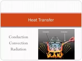
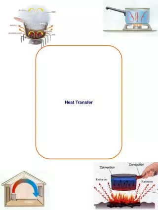
Heat Transfer in Microchannels. Applications. Cooling of microelectronics. Inkjet printer. 11.1 Introduction:. Medical research. Micro-electro-mechanical systems (MEMS): Micro heat exchangers, mixers, pumps, turbines, sensors and actuators.

E N D
Heat Transfer in Microchannels Applications Cooling of microelectronics Inkjet printer 11.1 Introduction: Medical research • Micro-electro-mechanical systems (MEMS): Micro heat exchangers, mixers, pumps, turbines, sensors and actuators
11.1.1 Continuum and Thermodynamic Equilibrium Hypothesis Properties: (pressure, temperature, density, etc) are macroscopic manifestation of molecular activity Continuum:material having sufficiently large number of molecules in a given volume to give unique values for properties Validity of continuum assumption: the molecular-mean-free path, , is small relative to the characteristic dimension of the system Mean-free-path: average distance traveled by molecules before colliding
(1.2) = characteristic length (1.3a) (1.3b) Knudson number Kn: Gases: the criterion for the validity of the continuum assumption is: Thermodynamic equilibrium: depends on collisions frequency of molecules. The condition for thermodynamic equilibrium is:
Microchannels: Channels where the continuum assumptionand/or thermodynamic equilibrium break down
(11.1) 9.1.2. Surface Forces. Examine ratio of surface to volume for tube: • For D = 1 m, A/V = 4 (1/m) • For D = 1 μm, A/V = 4 x 10 6 (1/m) • Consequence: • Surface forces may alter the nature of surface boundary conditions (2) For gas flow, increased pressure drop results in large density changes. Compressibility becomes important
(11.2) 9.1.3 Chapter Scope • Classification • Gases vs. liquids • Surface boundary conditions • Heat transfer in Couette flow • Heat transfer in Poiseuille flow 9.2 Basic Consideration 9.2.1 Mean Free Path. For gases:
Pressure drops along a channel increases Kn increases is very small, expressed in terms of the micrometer, p = pressure R = gas constant T = temperature μ = viscosity NOTE:
(6.57) (11.3) As 11.2.2 Why Microchannels? Nusselt number: fully developed flow through tubes at uniformsurface temperature Application: Water cooled microchips
(11.4) 11.2.3 Classification Based on the Knudsen number: Four important factors: (1) Continuum (2) Thermodynamic equilibrium (3) Velocity slip (4) Temperature jump
(1)Kn < 0.001: Macro-scale regime (previous chapters): Continuum: valid Thermodynamic equilibrium: valid No velocity slip No temperature jump (2) 0.001<Kn < 0.1: Slip flow regime: Continuum: valid Thermodynamic equilibrium: fails • Velocity slip • Temperature jump Continuity, Navier-Stokes equations, and energy equations are validNo-velocity slip and No-temperature jump conditions, conditions failReformulate boundary conditions
(3) 0.1< Kn<10: Transition flow: Continuity and thermodynamic equilibrium fail Reformulate governing equations and boundary conditions Analysis by statistical methods (4) Kn>10: Free molecular flow: analysis by kinetic theory of gases 11.2.4 Macro and Microchannels Macrochannels: Continuum domain, no velocity slip, no temperature jump Microchannels: Temperature jump and velocity slip, with or without failure of continuum assumption
Distinguishing factors: (1) Two and three dimensional effects (2) Axial conduction (3) Viscous dissipation (4) Compressibility (5) Temperature dependent properties (6) Slip velocity and temperature (7) Dominant role of surface forces
(1) Mean free path: 11.2.5 Gases vs. Liquids Macro convection: • No distinction between gases and liquids • Solutions for both are the same for the same geometry, governing parameters (Re, Pr, Gr,…) and boundary conditions Micro convection: • Flow and heat transfer of gases differ from liquids Gas and liquid characteristics: • Continuum assumption may hold for liquids but fail for gases
Typical MEMS applications: continuum assumption is valid for liquids (2) Knudsen number: used as criterion for thermodynamic equilibrium and continuum for gases but not for liquids (3) Onset of failure of thermodynamic equilibrium and continuum: not well defined for liquids (4) Surface forces: liquid forces are different from gas forces (5) Boundary conditions: differ for liquids from gases (6) Compressibility: liquids are almost incompressible while gases are not (7) Flow physics: liquid flow is not well known. Gas flow is well known
(8) Analysis: more complex for liquids than gases 11.3 General Features • Flow and heat transfer phenomena change as channel size is reduced: Rarefaction: Knudsen number effect Compressibility: Effect of density change due to pressure drop along channel Viscous dissipation: Effect of large velocity gradient Examine: Effect of channel size on: • Velocity profile • Flow rate
Friction factor • Transition Reynolds number • Nusselt number Consider: Fully developed microchannel gas flow as the Knudsen number increases from the continuum through the slip flow domain
(11.5) • Define friction coefficient (4.37a) 11.3.1 Flow Rate Slip flow: increased velocity and flow rate e = determined experimentally t = from macrochannel theory or correlation equations 11.3.2 Friction Factor f
= wall shear stress = mean velocity (11.6) = pressure drop • Fully developed flow through channels: define friction factor f D = diameter L = length
(11.7) Microchannels: compare experimental data, , with theoretical value, , (macroscopic, continuum) Macrochannels: fully developed laminar flow: (1) f is independent of surface roughness (2) Product of f and Reynolds number is constant for each channel geometry: Po = Poiseuille number (3) Po is independent of Reynolds number
(11.8) (1) departs from unity: Conclusion: (2) Unlike macrochannels, Po for fully developed flow depends on the Re (3) Conflicting findings due to: difficulties in measurements of channel size, surface roughness, pressure distribution, uncertainties in entrance effects, transition, and determination of properties
(6.1) Factors affecting the determination of 11.3.3 Transition to turbulent flow Macrochannels: smooth macrotubes Microchannels: reported transition • Variation of fluid properties • Measurements accuracy • Surface roughness
(11.9) 11.3.4 Nusselt number. For fully developed conditions: Macrochannel: Nusselt number is constant Microchannels: In general, Nusselt number is not well established: • Nu varies along microchannels • Nu depends on: • Surface roughness • Reynolds number • Nature of gas • Widely different reported results:
= experimental = macrochannel theory Factors affecting the determination of where: • Variation of fluid properties • Measurements accuracy
Slip flow regime: M = 11.4 Governing Equations Factors to be considered: • Compressibility • Axial conduction • Dissipation 11.4.1 Compressibility: Expressed in terms of Mach number
(6.30) Macrochannels: • Incompressible flow, M < 1 • Linear pressure drop Microchannels: • Compressible flow • Non-linear pressure drop • Decrease in Nusselt number 11.4.2 Axial Conduction Macrochannels: neglect axial conduction for
(11.10) Pe = Peclet number Microchannels: low Peclet numbers, axial conduction may be important, it increases the Nusselt number 11.4.3 Dissipation Microchannels: large velocity gradient, dissipation may become important 11.5 Slip Velocity and Temperature Jump Boundary Conditions Slip velocity for gases:
= fluid axial velocity at surface surface axial velocity = tangential momentum accommodating coefficient (11.11) = surface temperature x = axial coordinate n = normal coordinate measured from the surface Temperature jump for gases T(x,0) = fluid temperature at the boundary
, specific heat ratio = energy accommodating coefficient NOTE (1) Eq. (11.10) and (11.11) are valid for gases (2) Eq. (11.10) and (11.11) are valid forKn < 0.1 (3) σu and σT, are: • Empirical factors • They depend on the gas, geometry and surface • Values range from zero (perfectly smooth) to unity
Difficult to determine experimentally • Values for various gases are approximately unity
11.4. 8 Analytic Solutions: Slip Flows Two common flow types, extensive use in MEMS: (1) Couette flow (shear driven): fluid is set in motion by a moving surface Examples:
(2) Poiseuille flow (pressure driven): fluid is set in motion by an axial pressure gradient Examples: Micro heat exchangers, mixers, microelectronic heat sinks NOTE • No pressure drop in Couette flow • Signifiant pressure drop in Poiseuille flow Boundary conditions: two types: (1) Uniform surface temperature (2) Uniform surface heat flux
11.6.1 Assumptions (1) Steady state (2) Laminar Flow (3) Two-dimensional (4) Slip flow regime (0.001 < Kn < 0.1) (5) Ideal gas (6) Constant viscosity, conductivity and specific heats (7) Negligible lateral variation of density and pressure (8) Negligible dissipation (unless otherwise stated) (9) Negligible gravity
(10) The accommodation coefficients are equal to unity, 11.6.2 Couette Flow with Viscous Dissipation: Parallel Plates with Surface Convection • Infinitely large parallel plates • Gas fills gap between plates • Upper plate: moves with velocity us • Lower plate: stationary, insulated • Convection at the upper plate • Consider dissipation and slip conditions
(11.12) Determine: (1) Velocity distribution (2) Mass flow rate (3) Nusselt number Find flow field and temperature distribution Flow Field • Normal velocity and all axial derivatives vanish • Axial component of the Navier-Stokes equations, (2.9), simplifies to
Boundary conditions: use (11.10), Set • Lower plate: n = y = 0 and (11.10) gives (g) (h) (11.14) • Upper plate: n = H – y, (9.10) gives Solution
(11.13) Kn is the local Knudsen number NOTE (1) Fluid velocity at the moving plate: set y = H in (11.14) Effect of slip: • Decrease fluid velocity at the moving plate • Increase fluid velocity at the stationary plate
(k) (11.15) (2) Velocity distribution is linear (3) Setting Kn = 0 in (11.14) gives the no-slip solution Mass Flow Rate m W = channel width Neglect variation of ρ along y, (11.14) into (11.15)
(11.16) (11.17) (11.18) • Flow rate is independent of the Knudsen number • Compare with macrochannel flow rate mo (k) into (11.15) This is identical to (11.16), thus
(l) Nusselt Number • Equivalent diameter for parallel plates,De = 2H • Nusselt number Heat transfer coefficient h:
(11.19) k = conductivity of fluid T = fluid temperature Ts = plate temperature NOTE (1) Fluid temperature at the moving plate, T (x,H), is not equal to surface temperature (2) h is defined in terms of surface temperature Ts
(11.20) (11.21) (3) Use temperature jump, (11.11), to determine Ts (4) For the upper plate, n =H – y, eq. (11.11) gives • Mean temperature Tm: defined in Section 6.6.2 • Neglect variation of cp and ρ along y, use (11.14) . for u and (11.15) for m
(11.22) (11.23) Determine temperature distribution: • Use energy equation, (2.15) • Apply above assumptions, note that axial derivatives vanish, (2.15) gives
(2.17) gives the dissipation function which simplifies to (11.24) (11.25) (m) (9.24) into (9.23) Boundary conditions Lower plate:
(n) (11.26) Upper plate: Use (920) to eliminate Ts Use velocity solution (9.14), solve for T
(p) (u) (w) where Velocity solution (11.14), temperature solution (11.26) giveTs , Tm and Nu
(11.27) Note the following regarding the Nusselt number (1) It is independent of Biot number (2) It is independent of the Reynolds number (3) Unlike macrochannels, it depends on the fluid (4) First two terms in the denominator of (11.27) represent rarefaction (Knudsen number). The second term represents effect of temperature jump
(11.28) (11.29) (5) Nusselt number for macrochannels, Nuo: set Kn = 0 in (11.27): Ratio of (11.27) and (11.28) NOTE: Ratio is less than unity
Uniform surface flux, 11.6.3 Fully Developed Poiseuille Channel Flow: Uniform Surface Flux • Pressure driven flow between parallel plates • Fully developed velocity and temperature • Inlet and outlet pressures are pi and po Determine: (1) Velocity distribution (2) Pressure distribution (3) Mass flow rate (4) Nusselt number
Note: (3) Invariant axial velocity (4) Linear axial pressure Major difference between macro and micro fully developedslip flow: Macrochannels: incompressible flow (1) Parallel streamlines (2) Zero lateral velocity component (v = 0)
density changes • (2) Large axial pressure drop compressible flow (3) Rarefaction: pressure decreases increases Kn increases with x Microchannels: compressibility and rarefaction change above flow pattern: • (1) None of above conditions hold • (4) Axial velocity varies with axial distance (5) Lateral velocity v does not vanish • (6) Streamlines are not parallel (7) Pressure gradient is not constant