Download
1 / 17
170 likes | 332 Views
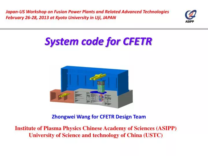
Japan-US Workshop on Fusion Power Plants and Related Advanced Technologies February 26-28, 2013 at Kyoto University in Uji , JAPAN. System code for CFETR. Zhongwei Wang for CFETR Design Team. Institute of Plasma Physics Chinese Academy of Sciences (ASIPP)

E N D
Japan-US Workshop on Fusion Power Plants and Related Advanced Technologies February 26-28, 2013 at Kyoto University in Uji, JAPAN System code for CFETR Zhongwei Wang for CFETR Design Team Institute of Plasma Physics Chinese Academy of Sciences (ASIPP) University of Science and technology of China (USTC)
Contents • Introduction • Need of a system code • Highlights of a system code • Configuration • Control module • Physical module • Engineering module • Standard and material database • Integration platform • Example: TF and VV workflow • TF coil engineering module GUI demo • Summary
Introduction • CFETR (China Fusion Engineering Test Reactor) aims at the fusion power plant, which requires long duty time and self-sufficient fuel supply, many groups join this project and cooperation. • To increase the design efficiency among different design groups and fit the requirement of commercial operation of fusion energy, the design process should be integrated and standardized as much as possible. • A system code could greatly realize the functions, it reflects the experience deposition of the fusion device from experimental to commercial.
Need of a system code • Data communications between different groups cost time • Each group has their own understanding on the information • Different strategies may be made according to the members’ experience • Accumulated margin in each step may make the design difficult to converge • Due to the lack of a fixed plan, schedule can not be ensured
Highlights of a system code • Automatic data transfer between different modules in standard formats • Independent design modules with good flexibility of software choice • No need for specific software training • Inheritance of mature design experience, automatic and manual judgments and iteration • Complete material and standard reference • Easy and clear control panel and workflow
Configuration • The system code consists of 5 main modules • Control module (interface, judgment and iteration) • Physical module • Engineering module • Standard database • Material database • The software tools run on the code include CAD, physical codes (DINA, EFIT, B2…) and engineering tools (ANSYS, FLUENT, ADAMS…), user-defined tools are also valid.
Control module • This is the key module of the system code, it covers the design workflow, transfers standardized data, makes choice and judgment and control optimization iteration. • Only this module has human-machine interface to the user, who is not required to be professional with the calculation software, then his attention could be focused on the key issues like defining design parameters and making decision.
Physical module • This module defines the reactor’s physical design, including these sub-modules • Plasma transport calculation; • MHD equilibrium calculation; • MHD stability calculation; • Heating power calculation; • Neutron distribution calculation; • System economical effect estimation. • These modules do not only setup and optimize the reactor’s concept, but also send data to the engineering module as load specification.
Engineering module • This module turns a concept reactor to a reality one, the sub-modules include • Magnet design (TF, PF, CS) • Blanket and divertor design • Vacuum vessel design • Cryostat/thermal shield design • Remote handling design • Cost estimation
Standard and material database • A series of standards must be setup for the reactor to ensure the design quality; the standard module includes both general industry standards and fusion specific ones, user-defined rules can also be added for special problems. • All modules should share standard material properties and R&D results, the material database allows the user to select in a dropdown list , meanwhile user-defined property is supported for optimization.
Integration platform • The system code is not only a software, but also a platform, the physical and engineering module call many other tools to do analysis, and these tools can be adjusted or replaced, with fixed I/O format of data/conclusion. • This character rises the flexibility, allows the user to modify the system code with kinds of resources, for example, EFIT calculates coil current, manual code sets up skeleton, CATIA generates the model and ANSYS performs mechanical analysis.
Example: TF coil • TF coil design moduleworkflow Material property Material limit Physical check Mechanical standard
Example: VV • VV design module workflow: Heat load to VVTS Material property Mechanical standard
Menu Magnet design Physical input: Major radius=? m Minor radius=? m Toroidal field= ? T Geometry input: Supporting structure concept design Working condition input: Temperature=? K Load from previous step: EM loads in normal operation, fast charge… Envelop from last step: Number of turn=? Outer diameter=? m Current per turn=? kA Peak magnetic field=? T Conductor design Engineering input: Blanket envelop=? m Vacuum vessel thickness=? m VVTS thickness=? m Distance between components= ? M Number of coils=? Choose case material: SS316L, Inconel alloy… Choose design criteria: ASME, RCC… Structure design Conductor parameters: Number of SC wire; Number of Cu wire; Quench temperature margin Choose material: NbTi, Nb3Sn… Assumed pulsed thermal load=? J O D Superconducting Structural results Judgment Resistive
Summary • A system code could increase the design efficiency and ensure the quality, meanwhile make the progress fit the schedule. • The control module summarizes existing experience and guides the design process. • The calculation tools in the physical and engineering modules are free to adjust or replaced. • Common standard and material database unites baseline information and saves time for checking. • The system code is easy to use and update, the user can focus on the critical issues.