Download
1 / 37
370 likes | 469 Views
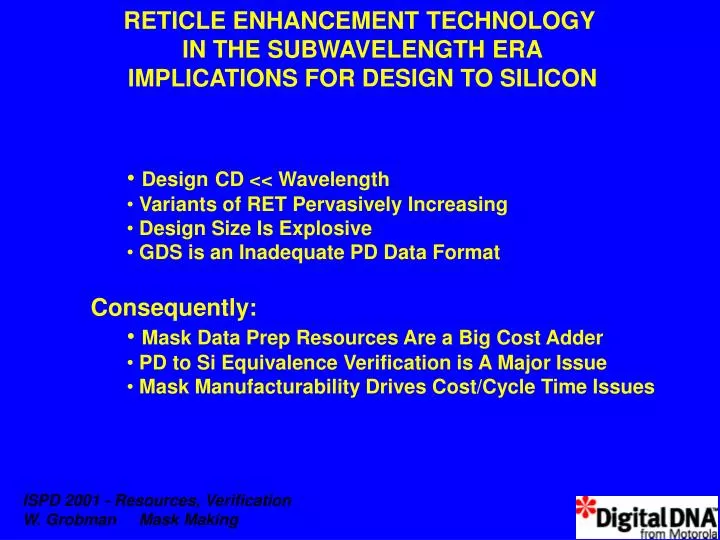
RETICLE ENHANCEMENT TECHNOLOGY IN THE SUBWAVELENGTH ERA IMPLICATIONS FOR DESIGN TO SILICON. Design CD << Wavelength Variants of RET Pervasively Increasing Design Size Is Explosive GDS is an Inadequate PD Data Format Consequently: Mask Data Prep Resources Are a Big Cost Adder

E N D
RETICLE ENHANCEMENT TECHNOLOGY IN THE SUBWAVELENGTH ERA IMPLICATIONS FOR DESIGN TO SILICON • DesignCD << Wavelength • Variants of RET Pervasively Increasing • Design Size Is Explosive • GDS is an Inadequate PD Data Format • Consequently: • Mask Data Prep Resources Are a Big Cost Adder • PD to Si Equivalence Verification is A Major Issue • Mask Manufacturability Drives Cost/Cycle Time Issues
Tile OPC Subwavelength RET: An Increasingly Important Post Tapeout Flow Behavioral & Logic Synthesis Formal & Func. Verification Phase Shift Complient Rules DFT, DFM, DFD, DFR Floorplanning , Place&Route Library Creation Noise, Power, Delay Extraction Phase Shift Methodology Layout , Parasitics A (GDSII) MaskPrep B (Post-RET GDSII) Mask Data Reticle Mfg Reticle Litho Process Si Process Si IC
Motorola Digital & RF Systems Roadmaps for Gate Length Extend Below Native Stepper Resolution Industry Roadmap Motorola Roadmap Stepper Wavelength Chart Courtesy of Numerical Technologies, Inc.
Summary - Reticle Enhancement Technology Optical Proximity Correction (OPC) Add shapes to design data (GDS II) Corrects for litho optics & process Rule based OPC - one mode fits all Model-based OPC - customized to shape neighborhood Phase-Shift “Strong” PSM - Phase mask + binary (“cut”) mask Used for gate printing CD, sheet rho, control “Weak” PSM - Via clear areas include attenuator Tiling Rule based tiling - Doesn’t guarantee global planarity Model-based tiling - POR for future reticles
OPTICAL PROXIMITY CORRECTION IMPROVES PRINTING (ADDS SHAPES TO MASK) MASK WAFER No OPC With OPC Photo downloaded from MicroUnity (now ASML MaskTools) web site
Rule-Based OPC Fig. 1A Fig. 1B
180 o phase-shifter 0.11mm Phase-Shifting Mask • Uses phase-modulation at the mask level to further the resolution capabilities of optical lithography • Benefits: • Smaller feature sizes • Improved yield (process latitude) • Dramatically extended useful life of current equipment • Performance Boost • Chip Area/Cost Advantage for Embedded Systems Printed using a ~0.18 mm nominal process
Phase Shift - Simple Idea, Complex EDA Challenge Chrome Etch (phase plate) Routing poly Legend: Grey= Opaque Color= Clear Binary Mask Clear Area 180 Phase Etch (phase plate) Gate
Done with Boolean operations Only density of the template is variable Not adequate for arbitrary design Rule-Based Tiling +
Model-Based Tiling • Different amount of tiles at different locations • Uses Linear Programming and in-house software
Model-Based Tiling - Large Manuafacturability Enhancement Untiled reticle (768A) (unmanufacturable) Conventional Rule-Based Tiling (702A) (9% uniformity improvement) 193 nm ASML Stepper N.A. = 0.85!!! Model-Based Tiling (152A) (80% uniformity improvement)
RET is Increasingly Driving New Issues • Design Release Data Prep Resources • Computation Time • CPU Time • Storage Requirements • PD to Si Equivalence Verification • Design Changes AFTER DRC/LVS/Timing/Power • Mask Manufacturability • Mask Fabrication Cycle Time & Cost
RET Methods Pervasively Expand as Technology Nodes Evolve “Prototypical” Scenario 0.25 um 0.18 um 0.13 um 0.10 um 0.07 um Rule-based OPC Model-based OPC Scattering Bars AA-PSM Weak PSM Rule-based Tiling Optimization-driven MB Tiling Number Of Layers Increases / Generation 248 nm 248/193 nm 193 nm
Main Drivers of RET Issues 0.25 um 0.18 um 0.13 um 0.10 um 0.07 um Rule-based OPC Model-based OPC Scattering Bars AA-PSM Weak PSM Rule-based Tiling Optimization-driven MB Tiling Data File Size, Computation Time, Mask Mfgbility Design Constraints, Mask Mfgbility, Mfg Complexity Computation Time, File Size, Timing/Power Reverification 248 nm 248/193 nm 193 nm
RET RESOURCES BLOAT (1997=1) 1000 Data Size/ Level Hours/design 100 # CPU’s # Layers 10 Mask Production (Days) 1 1997 1998 1999 2000 2001 (Est.)
MPU Lpoly (nm) Mask Min. Image Mask OPC Feature Mask / Si Dimensions (Source: ITRS) 1000 200 Dimension (nm) 100 50 10 1999 2000 2001 2002 2003 2004 2005 2006 2007 2008 2009 2010 2011 2012 2013 2014 Year
MPU Lpoly (nm) Mask Min. Image Mask OPC Feature Mask Metrology Dimensions for RET Implementation Are Significantly Smaller than Predicted by ITRS Roadmaps 1000 200 Dimension (nm) 100 ITRS Mask Min. Feature Assumption 50 RET-Driven Mask Min. Feature 10 1999 2000 2001 2002 2003 2004 2005 2006 2007 2008 2009 2010 2011 2012 2013 2014 Year
Solutions • Reticle Delivery Cycle • - Model-Driven Mask Inspection • PD to Si Integrity • - Model Si AND Mask Process • - Use to Drive Si vs. PD Virtual Validation • Intelligent OPC • - ID Critical Design Features • - Apply MB-OPC With Discrimination • Use Parallel Processing • - Recapture Hierarchy For Compaction • and Functional Validation (e.g. Timing) • Retain Design Data in PD Representation • - GDS Replacement Open Standard
Defectivity is the most serious problem affecting reticle delivery More acute with the introduction of OPC OPC features do not resolve as drawn in the design on reticle When inspected, OPC results in vast numbers of false defect detections Worst case (currently typical), the mask cannot be inspected at all Standard practice: De-sense reticle inspection tool so partially resolved OPC shapes do not cause errors De-sensing for OPC also de-senses the tool to legitimate defects RETICLE INSPECTION ISSUES Overlay of sample design data (red), OPC data (yellow), and reticle image on inspection tool (white) Reticle Image on Inspection Tool Original Data with Serifs From Kling, Lucas Motorola Patent
OPC RETICLE INSPECTION INNOVATIONS • Create a data set separate from the design to mimic shrinkage and rounding of OPC structures on reticle • The only change from written data is that OPC structures are altered for inspectability • The altered data set is presented to the inspection tool • Essentially we are inspecting to an image that depicts the reticle as it is expected to appear after exposure transformations and chemical processing Database image with inspection shapes on inspection tool Reticle image on inspection tool Original data with serifs Data with inspection shapes From Kling, Lucas Motorola Patent
RET Must Incorporate Virtual Stepper AND Virtual Maskwriter PD MASK WAFER No OPC With OPC With Mask-Model Based OPC
Si ~ Layout - Separate Mask and Wafer Process Models Improve Manufacturability / Flexibility Layout to Si Common Today MASK process model Improve Mask Inspection Fix Linearity Bias (Small vs. large feature) (Esp. bad at metal: xtalk, intralevel shorts… ) Fix E-beam writer artifacts Courtesy: Numerical Technologies, Inc. = This Paper’s Suggested strategy
Tile OPC Model-Driven (MD) RET - MD Data Processing - MD Verification Behavioral & Logic Synthesis Formal & Func. Verification Phase Shift Complient Rules DFT, DFM, DFD, DFR Floorplanning , Place&Route Library Creation Noise, Power, Delay Extraction Phase Shift Methodology Layout , Parasitics A (GDSII) MaskPrep B (Post-RET GDSII) Mask Data MODELS Reticle Mfg Reticle Litho Process Si Process Si IC
Proper Models -> Local Design Integrity Wafer Image Simulation Layout with OPC OPC Verification Printed Wafer Identify Critical Design FeaturesApply OPC With Discrimination & Verify Si=PD Courtesy: Numerical Technologies
Intelligent MB-OPC is Desirable Add Vertices Only for Manufacturability e.g. Apply OPC With Discrimination 44 Vertices Today Critical - Requires MBOPC Better 20 Vertices Simply Must Avoid Pullback
Partitioning for Parallel Processing Use Hierarchy (Library Cells) AND/OR Flatten and use explicit proximity effect range (Global Wire / Custom) Calculate OPC In Here Keep Solution in Here
PROCESSING THROUGHPUT AND COST R E T Today’s Model Cluster N-Way Processor Shared Memory Full-chip Hours -> Days / Run ~ $500K System Not Easily Scaleable Conventional License Model N Linux Nodes Distributed Memory Loose Multithreading (Optical / EM Effects are Short Range Compared to Compute Cell Size) Hours / Run ~ N X $2000 System Simple to Scale --> Need New License Model
Storage / Data Transmission “Explosion” It’s Desirable to Compress Data Post RET • MB-OPC Breaks Hierarchy • Recapture Hierarchy by One or Both of: • 1. Hierarchical Data Incorporated in Design Shapes • GDS Is an Interchange Format • Need Representation which Couples Physical with Other Design Attributes • Examples: SI2 Open Library API, Cadence Genesis • 2. Use Pattern Extraction Heuristics to Identify Arrays of Shapes • Can be Computationally Very Efficient - O(N) CPU time where N is the Number of Shapes • Available Now - Here’s a Quick Demo
Example: Pattern Extraction Heuristic to Regain Hierarchy Start With Flat Data File of Sequential Records, Sort to Get Contiguous Records Of Same Shape, Different x,y Positions y x opcode1 Shape Attributes y x opcode1 Shape Attributes y x opcode1 Shape Attributes . . . . y x Opcode-k Shape Attributes y x Opcode-k Shape Attributes y x Opcode-k Shape Attributes y x Opcode-k Shape Attributes y x Opcode-L Shape Attributes y x Opcode-L Shape Attributes Sort1 Sort2
Example: Pattern Extraction Heuristic to Regain Hierarchy 2000 Random Points + 9 X 7 Array
Example: Pattern Extraction Heuristic to Regain Hierarchy After 1 Pass of Heuristic
Example: Pattern Extraction Heuristic to Regain Hierarchy After Second Pass of Heuristic
Post-Parallel Processing Compaction and Verification • Pattern Recognition Heuristics Can Be Very Effective for Compaction • This is Important for Efficient Data Delivery to Mask Shop • BUT • Timing, Power, … Checking for Tiled Design Requires An Even Better Connection of PD Data to Design • Global Nets May Need Timing Verification after Tiling • Consequently, RET Could Drive Industry to More Quickly Adopt a New Standard Useful for PD Re-Timing After RET
Workstation Hierarchical PD Hierarchical PD Rule-based OPC c:PSM Si vs PD (mask and litho models) Flatten & Partition Parallel Processors • Smart MB-OPC • Tiling Partitioned Flat PD for Parallel Computation (OLA-like PD Data Representation) Timing/Power Verify Data Compaction Create Mask Inspect Data Mask Data Mask Inspect Data Example RET Design Flow Scenario
Robust, Implementable RET Design Requires New Paradigms • RET Requires Models of New Types - Closer to Fabrication • Accurate PD -> Mask -> Si Models • Drive Design Reverification • Drive Mask Inspect Data for Mask Cycle Reduction • Parallel Computation Can Shrink Compute Resources • Recapture of Hierarchy Shrinks Data Size • Recapture of Design Structure Drives Global Timing Verification