Download
1 / 31
590 likes | 2.04k Views
Fiber Optic Connectors, Splices, and Tools. Ch 6 Fiber Optics Technician’s Manual, 3 rd . Ed Jim Hayes. Fiber Joints. Fibers must be joined when You need more length than you can get on a single roll Connecting distribution cable to backbone Connecting to electronic source and transmitter

E N D
Fiber Optic Connectors, Splices, and Tools Ch 6 Fiber Optics Technician’s Manual, 3rd. Ed Jim Hayes
Fiber Joints • Fibers must be joined when • You need more length than you can get on a single roll • Connecting distribution cable to backbone • Connecting to electronic source and transmitter • Repairing a broken cable
Splices v. Connectors • A permanent join is a splice • Connectors are used at patch panels, and can be disconnected
Optical Loss • Intrinsic Loss • Problems the splicer cannot fix • Core diameter mismatch • Concentricity of fiber core or connector ferrules • Core ellipticity • Numerical Aperture mismatch • Images from LANshack and tpub.com (links Ch 6a & 6c)
Optical Loss • Extrinsic Loss • Problems the person doing the splicing can avoid • Misalignment • Bad cleaves • Air gaps • Contamination: Dirt, dust, oil, etc. • Reflectance
Measuring Reflectance • The reflected light is a fraction of the incoming light • If 10% of the light is reflected, that is a reflectance of 10 dB • If 1% of the light is reflected, 20 dB • Reflectance is not usually a problem for data networks, but causes ghosting in analog cable TV transmission • Angled connectors reduce reflectance
Connectors • There are four types • Rigid Ferrule (most common) • Resilient ferrule • Grooved plate hybrids • Expanded beam • Top image shows ferrules from swiss-jewel.com (link Ch 6e) • Lower image shows LC, SC, Biconic, and the obsolete Deutsch 1000 • From thefoa.org (link Ch 6d)
Rigid Ferrule Connectors • 2.5 mm ferrule • ST • SC • FC • Images from thefoa.org (link Ch 6d)
Rigid Ferrule Connectors • 1.25 mm ferrule • Small Form Factor • LC • MU • LX-5 • Images from thefoa.org (link Ch 6d)
Obsolete Connectors • Simplex (1-fiber) • SMA • D4 • Biconic • Images from thefoa.org (link Ch 6d)
Duplex Connectors • Old, bulky • FDDI • ESCON • Images from thefoa.org (link Ch 6d)
Duplex Connectors • Newer, smaller • Small Form Factor • MT-RJ • Opti-Jack • Volition • Images from thefoa.org (link Ch 6d)
Duplex Connectors • New, popular • Small Form Factor • Duplex LC • Images from globalsources.com (link Ch 6f)
Ferrule Polish • To avoid an air gap • Ferrule is polished flat, or • Rounded (PC—Physical Contact), or • Angled (APC) • Reduces reflectance • Cannot be mated with the other polish types • Image from LANshack (link Ch 6a)
FOCIS • Fiber Optic Connector Intermateability Standard • A document produced by a connector manufacturer so others can mate to their connector • Connectors with the same ferrule size can be mated with adaptors • But 2.5 mm ferrules can not be mated with 1.25 mm ferrules
Telecommunications • In telecommunications, SC • and FC • are being replaced by • LC • in the USA • MU • in other countries
Data • In data communications, SC and ST • are being replaced by • LC
Connectorizing a Cable • Epoxy-polish process (Proj. 4) • Strip cable, strip and clean fiber • Inject adhesive, put primer on fiber, insert fiber • Crimp connector, cleave protruding fiber • Air polish, final polish • Clean and inspect by microscope • Test connector loss with power meter
Cable Type and Connectors • Epoxy-polish process requires a cable jacket and strength member to make the connector durable • It works for simplex, zip, or breakout cables • But loose-tube cables and ribbon cables contain bare fiber, and cannot be connectorized this way • Distribution cables contain 900 micron buffered fiber – can be connectorized, but the connectors are not very strong and must be protected by hardware such as a junction box
Breakout Kit • Provides tubing that protects the bare fiber so it can be terminated • Picture from fonetworks.com (link Ch 4d)
Mounting Methods for Connectors • Adhesives • Epoxy (room temperature-cure or oven-cure) • Quick-curing anaerobic adhesives (we used this method in Proj 4) • Hot-Melt adhesive • Crimping to hold the fiber • Like the Unicam – see link Ch 6h • Splicing to preconnectorized pigtails • Image of pigtail from fiberdyne.com (link Ch 6g)
Mounting Methods Comparison • Epoxy-Polish • Takes longer, but costs less and has lowest loss and reflectance • Anaerobic adhesive • Faster than epoxy-polish but higher loss because polishing is difficult • Crimping • Easier, but more expensive and more loss • Splicing to preconnectorized pigtail • Very easy, but expensive and higher loss
Strip, Clean and Cleave • Strip – remove 900 micron buffer (if present) and 250 micron coating • Clean with alcohol and lint-free wipe • Cleave – scribe and snap; goal is a 90 degree flat break
End-Face Polish • Polish on a flat glass plate for a flat finish • Polish on a rubber mat for a domed PC finish (Physical Contact) • Angled PC finish is tilted at 8 degrees to avoid reflectance (difficult to field-terminate)
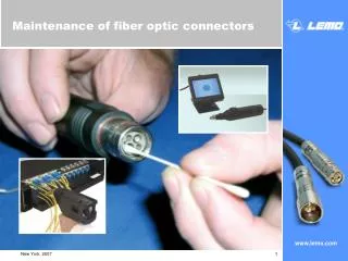
Cleaning Connectors • Keep dust caps on • Use lint-free wipes and reagent-grade isopropyl alcohol to avoid attacking epoxy • “Canned air” has propellant, so does compressed air from a hose
Splices • Splices are a permanent join of two fibers • Lower attenuation and reflectance than connectors • Stronger and cheaper than connectors • Easier to perform than connectorization • Mass splicing does 12 fibers at a time, for ribbon cables
Mass Fusion Splicing • Video from fitel.fiberoptic.com (link Ch 6i)
Fusion Splicing • Melts the fibers together to form a continuous fiber • Expensive machine • Strongest and best join for singlemode fiber • May lower bandwidth of multimode fiber • Corning videos 1-7 & 12
Mechanical Splicing • Mechanically aligns fibers • Contains index-matching gel to transmit light • Equipment cost is low • Per-splice cost is high • Quality of splice varies, but better than connectors • Fiber alignment can be tuned using a Visual Fault Locator
Tools • We covered them in Project 2