Download
1 / 1
10 likes | 90 Views
Low Background 222 Rn Counting for the Large Underground Xenon Dark Matter Detector. J. Verbus , T . Shutt Department of Physics, Case Western Reserve University. Abstract

E N D
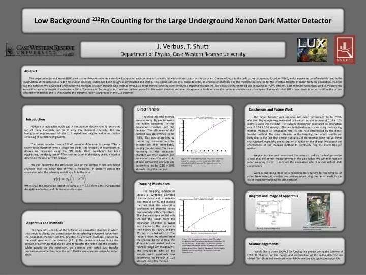
Low Background 222Rn Counting for the Large Underground Xenon Dark Matter Detector J. Verbus, T. Shutt Department of Physics, Case Western Reserve University Abstract The Large Underground Xenon (LUX) dark matter detector requires a very low background environment in its search for weakly interacting massive particles. One contributor to the radioactive background is radon (222Rn), which emanates out of materials used in the construction of the detector. A radon emanation counting system has been designed, constructed and tested. This system consists of a radon detector, an emanation chamber and the mechanism required for the effective transfer of radon from the emanation chamber into the detector. We developed and tested two methods of radon transfer. One method involves a direct transfer and the other involves a trapping mechanism. The direct transfer method was shown to be ~99% efficient. Both methods were then used to measure the emanation rate of a sample of unknown activity. The intended future goal is to reduce the background in the radon detector and use this apparatus to determine the radon emanation rate of samples of several critical LUX components in order to allow the proper selection of materials and to characterize the expected radon background in the LUX detector. Conclusions and Future Work The direct transfer measurement has been determined to be ~99% effective. The sample was measured to have an emanation rate of 0.15 ± 0.03 atoms/s using this method. The trapping mechanism measured an emanation rate of 0.04 ± 0.04 atoms/s . The best individual runs to date using the trapping method measure an emanation rate ~½ the rate determined by the direct transfer method. The inconsistencies in the trapping mechanism results are likely due to the fact that certain subtleties of the method have not yet been characterized, especially the adsorption of radon on the SS trap. We expect the effectiveness of the trapping method to eventually rival the direct transfer method. We plan to clean and reconstruct the system to reduce the background to a level that will permit measurements in the μBq range. We will then use the radon counting system to measure the emanation rate of several critical LUX components. Work is also being done on a complimentary system for the removal of radon from water. A possible use involves monitoring the radon levels in the water shield surrounding the LUX detector. Introduction Radon is a radioactive noble gas in the uranium decay chain. It emanates out of many materials due to its very low chemical reactivity. The low background requirements of the LUX experiment require radon emanation screening of detector components. The radon detector uses a 2.8 kV potential difference to sweep 218Po, a radon decay daughter, onto a silicon PIN diode. The energies of subsequent α-decays are measured using the PIN diode. Once equilibrium has been established, the decay rate of 214Po, another atom in the decay chain, is used to determine the rate of 222Rn decays. We can determine the emanation rate of the sample in the emanation chamber once the decay rate of 222Rn is measured. In order to obtain the emanation rate, the following equation is fit to the data: Where is the emanation rate of the sample, is the characteristic decay time of radon, and t is the emanation time. Direct Transfer The direct transfer method involves using N2 gas to sweep the radon contained in the emanation chamber into the detector. The efficiency of this method was determined to be ~99%. This was determined by transferring the radon into the detector and then immediately purging the detector. The radon remaining in the emanation chamber was then assayed. The emanation rate of a small chip of rock containing uranium was determined to be 0.15 ± 0.03 atoms/s using this method. Figure 1: Fit of direct transfer data. The radon emanation rate of the sample was determined to be 0.15 ± 0.03 atoms/s. 0.15 ± 0.03 atoms/s. The reported errors are statistical only. Trapping Mechanism The trapping mechanism utilizes a synthetic activated charcoal trap and a stainless steel trap in series, and exploits the fact that the adsorption coefficient of charcoal varies exponentially with temperature. The charcoal trap is cooled with LN and the radon from the emanation chamber is swept into the trap. The charcoal is then heated to ~130oC and the SS trap is cooled with LN. The radon is then transferred from the charcoal to the SS trap. The SS trap is then heated, and the radon is swept into the detector. The emanation rate of the sample used previously was determined to be 0.04 ± 0.04 atoms/s using this method. Diagram and Image of Apparatus Apparatus and Methods The apparatus consists of the detector, an emanation chamber in which the sample is placed, and a mechanism for transferring emanated radon from the emanation chamber into the detector. A significant challenge is posed by the small volume of the detector (1.3 L). The detector volume limits the amount of carrier gas that can be used to transfer the radon into the detector. While considering this restriction, we designed and tested two transfer mechanisms in order to create the most flexible and effective system for radon assay. Figure 4: Image of apparatus; traps, detector, and emanation chamber. Figure 3: Diagram of Apparatus Acknowledgements I would like to thank SOURCE for funding this project during the summer of 2008, N. Shaman for the design and construction of the radon detector, my advisor Tom Shutt and everyone in our lab for making this opportunity possible. Figure 2: Fit of trapping mechanism data. The radon emanation rate of the sample was determined to be 0.04 ± 0.04 atoms/s. The discrepancy in the data is due to subtleties in the transfer process that have not yet been characterized. More than half the radon is lost during the transfer using this method. The reported errors are statistical only.