Download
1 / 34

E N D
The ILC Control System J. Carwardine, C. Saunders, N. Arnold, F. Lenkszus (Argonne), K. Rehlich, S. Simrock (DESY), B. Banerjee, B. Chase, E. Gottschalk, P. Joireman, P. Kasley, S. Lackey, P. McBride, V. Pavlicek, J. Patrick, M. Votava, S. Wolbers (Fermilab), K. Furukawa, S. Michizono (KEK), R.S. Larsen, R. Downing (SLAC)
Content • ILC overview • Controls challenges and conceptual design • Availability • Services • Configuration management • Collaboration • Wrap-up
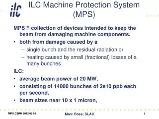
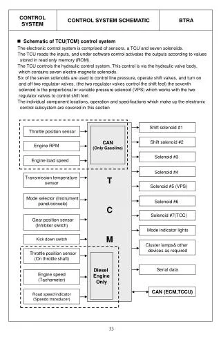
ILC accelerator overview • Two 11km long 250-GeV linacs with 16,000 cavities and 640 RF units. • A 4.5-km beam delivery system with a single interaction point. • 5-GeV electron and positron damping rings, 6.7km circumference. • Polarized PC gun electron source and undulator-based positron source. J. Bagger
2006 2010 2014 2018 Engineer Design Construction Start-up BCD Begin Const End Const RDR EDR Siting Plan being Developed Detector Construct Detector Install Site Select Site Prep Pre-Operations All regions ~ 5 yrs R & D -- Industrialization System Tests & XFEL Gradient Cryomodule Full Production August e-Cloud Technically Driven Timeline
Control System challenges • Mainly driven by scale & complexity of ILC accelerators • 100,000 devices, several million control points • Main linacs: 640 RF klystrons, 2000 cryomodules, 16,000 cavities • Control system: 1000+ front-end crates • Accelerator operations: reliance on automation & feedback • Accelerator availability goal of 85% (control system: 99%) • Precision timing & synchronization over 10’s km. • Remote operations. • ILC funding model: multi-national in-kind contributions.
Control System functional model • Client Tier • GUIs • Scripting • HMI for high level apps • Services Tier • “Business logic” • Device abstraction • Feedback engine • State machines • Online models… • Front-End Tier • Equipment Interfaces • Control-point level
Addressing the challenges • Large scale deployment • High Availability, strong emphasis on diagnostics, QA. • Resource management • Emphasize standards-based solutions. • Extensive reliance on automation and 5Hz feedback • Automation and feedback engines as Services. • Make all control & monitor points available to feedback engine, synchronize control and monitor actions to 5Hz beam pulses. • Controls integration of in-kind contributed equipment • Scope, span of control, treaty points… • ?
Availability • ILC control system availability goal: 99% by design • 1000+ front-end crates 99.999% per crate. • Cannot afford a long period of identifying & fixing problems once machine operations begin. ‘Best effort’ approach may not be sufficient Investigate High Availability techniques.
Accelerator Availability • Accelerator availability goal: 85% • Control system availability goal: 99% • Requires intrinsic reliability + rapid recovery
HA requires different considerations • Apply techniques not typically used on an accelerator • Development culture must be different. • Cannot build ad-hoc with in-situ testing. • Build modeling, simulation, testing, and monitoring into hardware and software methodology up front. • Hardware availability • Instrumentation electronics to servers and disks. • Redundancy where feasible, otherwise adapt in software. • Modeling and simulation • Software availability • Equally important. • Software has many more internal states – difficult to predict. • Modeling and simulation needed here for networking and software. • Robustness • Exception handling.
Relative cost/benefit of HA techniques 13. Automatic failover Availability (benefit) 12. Model-based automated diagnosis 11. Manual failover (eg bad memory, live patching) 10. Hot swap hardware 9. Application design (error code checking, etc) 8. Development methodology (testing, standards, patterns) 7. Adaptive machine control (detect failed BPM, modify feedback) 6. Model-based configuration management (change management) 5. Extensive monitoring (hardware and software) 4. COTS redundancy (switches, routers, NFS, RAID disks, database, etc.) 3. Automation (supporting RF tune-up, magnet conditioning, etc.) 2. Disk volume management 1. Good administrative practices Cost (some effort laden, some materials laden) C. Saunders
HA R&D objectives • Learn about HA (High Availability) in context of accelerator controls • Bring in expertise (RTES, training, NASA, military, …) • Explore standards-based methodologies • Develop (adopt) a methodology for examining control system failures • Fault tree analysis, FMEA, scenario-based FMEA • Others… • Develop policies for detecting and managing failure modes • Development and testing methodology • Instrumentation, out-of-band monitoring (independent diagnostics) • Workarounds • Redundancy • Develop “vertical” prototypes • Ie. how we might implement above policies • Integrate portions of “vertical” prototypes with accelerator facilities
Front-end electronics requirements • HA-specific requirements • Intelligent Platform Management • Remote power on/off and reset/initialize for individual boards. • Highly improved diagnostics capabilities in all electronics subsystems. • Support redundancy: processors, comms links, power supplies,… • Hot-swappable components: circuit boards, fans, power supplies, … • Platform basic requirements • Standard modular architecture • Broad industry support of core components • Wide range of COTS modules + support custom instrumentation. • ‘High performance’ + cost-effective.
If not VME or VXI, then what…? • Candidate standards include ATCA, uTCA, VME64x, VXS, VPX, other VITA standards… • Of systems available today, ATCA offers the best representative feature set • Represents best practices of decades of telecom platform development. • Increasing evidence of commercial products for controls applications. • Growing interest in the Controls and DAQ community. • Being evaluated by several labs. Strong candidate for XFEL. • Two flavors • ATCA: Full-featured, large form-factor • uTCA: Reduced feature-set, smaller form-factor, lower cost.
ATCA crates 5-Slot Crate w/ Shelf Manager Fabric Switch Dual IOC Processors 4 Hot-Swappable Fans 16 Slot Dual Star Backplane Shelf Manager Dual 48VDC Power Interface Dual IOC’s Fabric Switch Rear View R. Larsen
IPMI, HPI, SNMP, others… SM Fault detection and remediation(“Shelf” Management) Client Tier Services Tier Controls Protocol • Shelf Manager: • Identify all boards on shelf • Power cycle boards (individually) • Reset boards • Monitor voltages/temps • Manage Hot-Swap LED state • Switch to backup flash mem bank • More… Custom CPU1 I/O CPU2 Front-end tier sensor C. Saunders
SAF Availability Management Framework • Open standard from telecom industry geared towards highly available, highly distributed systems. • Manages software runtime lifecycle, fault reporting, failover policies, etc. • Works in combination with a collection of well-defined services to provide a powerful environment for application software components. • Potential application to critical core control system software such as IOCs, device servers, gateways, name-servers, data reduction, etc. • Know exactly what software is running where. • Gracefully restart components, manage state for component hot-swap • Uniform diagnostics to troubleshoot problems. • Implementations: OpenClovis, OpenSAF, Self-Reliant, Element, … C. Saunders
SAF – Availability Management Framework A simple example of software component runtime lifecycle management Service Unit Administrative States AMF Logical Entities Node V Node U Service Group Unlocked Locked Service Unit Service Unit Component Component Component Component Locked- Instantiation Shutting down active standby 1. Service unit starts out un-instantiated. 2. State changed to locked, meaning software is instantiated on node, but not assigned work. Service Instance is work assigned to Service Unit Service Instance 3. State changed to unlocked, meaning software is assigned work (Service Instance). C. Saunders
HA software framework is just the start • SAF (Service Availability Forum) implementations won’t “solve” HA problems • You still have to determine what you want to do and encode it in the framework – this is where work lies • What are failures • How to identify failure • How to compensate (failover, adaptation, hot-swap) • Is resultant software complexity manageable? • Potential fix worse than the problem • Always evaluate: “am I actually improving availability?” • Where should we apply high availability techniques?
Configuration management Example: replacing circuit board
…underlying assumptions • Electronics board functions: • Hot-swappable • Remote reset / re-initialize. • Unique ID, available remotely • Remotely configurable (“DIP switches”) • Remotely updatable software, firmware, FPGA code • Separate Standby and Run modes • On-board self-test • RDB contains: • Information on all installed and spare electronics boards • Information for every crate / slot / location • Current version of all software, firmware, FPGA code
Applications Channel-Oriented Interface Service Interface MQP DOP General Purpose Network SRTP Service Interface Services Device Abstraction, Model Interaction, Archiving, Save/Restore, Feedback, Deployment & Mgmt, Automation, … DB Access RDB DBP Deployment & Mgmt. Interface Channel-Oriented Interface DMP SRTP Services Tier architecture Applications Graphical interfaces Operator consoles Client Tier Services Well defined high-level functions available to any application or other service Channel-oriented Interface Traditional high-performance, direct access to control points Engineering model Physics model Controls model Operational data DOP – distributed object protocol MQP – message queuing protocol SRTP – soft real-time protocol DBP – database protocol DMP – deployment & mgmt protocol Front-end Tier (not shown) C. Saunders
Why Services? • Some activities are not well suited to channel-oriented interfaces • Complex • May require lots of parameters and a sequence of interactions • Dynamic • May be added and removed frequently during operations • May require dynamic allocation (network latency and/or cpu loading) • It should be possible to create a well-defined interface for common control system functions. • Services allow rapid prototyping of high level apps through composition, while maintaining an an impedance to changing the core functions. • Someone is going to do this anyway
Script execution service Archiving service Logging service Data processing & visualization Save, Compare, Restore Alarm Management RDB calls Locking (channel, instance,…) Math & logic functions Event sequencer / synchronizer Device server Data concentrator Feedback / dynamical control Video processing, compression Out of Band monitoring Exception handling Resource management Authentication / access control Notification (email, phone, sms,…) Possible Services APIs
Example: Knob Service Sequence knob GUI front ends C. Saunders
Example: Feedback Service Sequence feedback GUI front ends C. Saunders
Services Tier realization… • Defining a Services Tier does not define where it runs • Front-end processors • Client workstations • Dedicated processors • Central servers • Interfaces are hard to define • API inputs, outputs. • Services dependencies.
Inherently an international collaboration Resource-limited (2-3 FTEs) Main collaborators: Argonne, DESY, Fermilab, KEK, SLAC Heavily reliant on activities at new and operating accelerators Benefit from existing work. Prototype & evaluate ideas and techniques. Strong connection with DESY XFEL, Fermilab ILCTA, KEK STF We need more people to support the Global Design Effort, contribute ideas, collaborate in developing & evaluating ideas. Collaboration
2008-2010 Work Package topics • Electronics platform evaluations (eg ATCA, uTCA) • High Availability • Risk analysis of design, FMEA • Services architecture development • Integrated software development on an international scale • Configuration management • Control System architecture design • Network simulation/modeling • Machine protection • Remote Operations • Evaluate potential controls integration tools • Cost optimization • Controls integration
Wrap-up • We have identified technical challenges that can be pursued now, and have created work packages that describe ways to address them. • There is more work than a few FTEs can do …we are looking for more collaborators ILC: www.linearcollider.org Controls: www.linearcollider.org/wiki