Download
1 / 10
100 likes | 238 Views
SCR/Thyrisitor. pnpn structure with 3 pn junctions. Cross-section of the pnpn structure. + V AK -. J1. J2. J3. I A = 0.

E N D
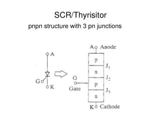
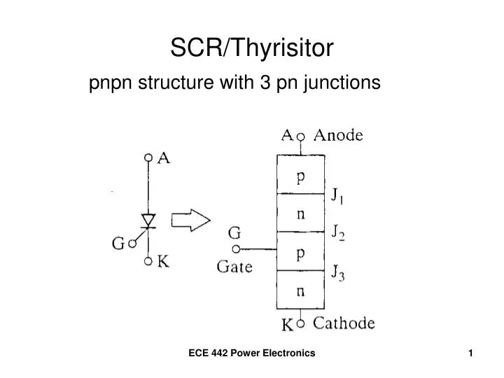
SCR/Thyrisitor pnpn structure with 3 pn junctions ECE 442 Power Electronics
Cross-section of the pnpn structure + VAK - J1 J2 J3 IA = 0 Apply a forward bias voltage to the Anode-Cathode Junctions J1 and J3 are forward biased Junction J2 is reverse biased Only a small amount of current flows from A to K The device is in it’s OFF or “Forward Blocking” State ECE 442 Power Electronics
SCR/Thyristor (continued) + VAK - IA Increase the Anode-Cathode voltage until “breakdown” occurs. Anode current increases. “Conducting state” ECE 442 Power Electronics
Thyristor Volt-Ampere Characteristic ECE 442 Power Electronics
Two-Transistor Model ECE 442 Power Electronics
Effects of Increasing Gate Current ECE 442 Power Electronics
Line-Commutated Thyristor Circuit ECE 442 Power Electronics
Forced-Commutated Thyristor Circuit ECE 442 Power Electronics
Triac – Bi-directional Thyristor ECE 442 Power Electronics
Triac Volt-Ampere Characteristic ECE 442 Power Electronics