Download
1 / 8
80 likes | 205 Views
Willem Jellema National Institute for Space Research of the Netherlands (SRON). Presented by - Neil Trappe National University of Ireland, Maynooth (NUIM). Acknowledge input from Robert Huisman (SRON) Tim Finn (NUIM). OUTLINE OF PRESENTATION.

E N D
Willem JellemaNational Institute for Space Research of the Netherlands (SRON) Presented by - Neil Trappe National University of Ireland, Maynooth (NUIM). Acknowledge input from Robert Huisman (SRON) Tim Finn (NUIM) FPU CDR July 1 - 3
OUTLINE OF PRESENTATION • 2 Aspects to verification of Optical performance - (1) Computational modeling. (2) Experimental Testing • Introduce Experimental Test facility set-up. • Results obtained for the Mixer Sub Assembly (MSA). • Initial Results for the Common Optics Path/ L.O. Path. • Plan of Future Work. (Experimental/Computational) • Summary and Conclusions FPU CDR July 1 - 3
Work already presented - • Initial computational analysis of HIFI already complete. • Verified optical – beam sizes, truncation … • Initial aberration analysis with software package GLAD. • Signal path. Aperture efficiency calculations • LO Path. Beam coupling calculations. • Old “Gaussicity” calculations < 1% different to exp. Results. • (PDR Delft April 2001) • This presentation - recent progress + future plans. • Use of software package GRASP8. FPU CDR July 1 - 3
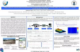
EXPERIMENTAL SETUP (1) • Test criteria • Resolve features with a characteristic scale of 1 mm at –20 dB • Measurement uncertainty smaller than 3 to 4 dB at –20 dB • Accuracy in main-beam better than 1 dB • Dynamic range larger than 30 dB • Measurement concept: • Coherent narrow-band detection of output beam (phase is also measured) • Signal chain based on harmonic mixer and phase-locked Gunn oscillator • Field is sampled along linear cuts by a probe on a scanner system FPU CDR July 1 - 3
EXPERIMENTAL SETUP (2) FPU CDR July 1 - 3
EXPERIMENTAL SETUP (3) • Corrugated horn design: • 2.5 mm aperture radius • 15.4 mm slant length • compliant with MSA optical I/F • adapted waveguide dimensions • optimised waveguide transition • optimised corrugation diameters • optimised corrugation widths • minimum return loss • low cross-polarisation • good E/H symmetry FPU CDR July 1 - 3
HORN MEASUREMENTS (1) Calculated and measured response for horn measured by probe FPU CDR July 1 - 3
EXPERIMENTAL SETUP (4) • Probe design: • Flared waveguide probe • TE10 mode + phase curvature • Aperture of 1.0 x 1.4 mm • Slant length of 10.7 mm • Spatial resolution of ½ mm-1 • Good E/H symmetry • High polarisation purity FPU CDR July 1 - 3