Download

1 / 50
500 likes | 534 Views
Learn about the concepts, principles, and activities of object-oriented analysis and design. Understand the steps involved in the object-oriented development life cycle and the deliverables produced. Includes use case diagrams, sequence diagrams, and class diagrams.

E N D
Modern Systems Analysisand DesignFourth EditionJeffrey A. Hoffer Joey F. GeorgeJoseph S. Valacich Appendix 3 Object-Oriented Analysis and Design
Learning Objectives • Define events, state transitions, and sequence diagrams. • Describe concepts and principles of object-orientation. • Describe activities of the different phases of object-oriented development. • Compare object-oriented modeling with traditional systems development approaches. • Develop dynamic models with state, interaction, and activity diagrams. • Model real-world applications with UML.
The Object-Oriented Development Life Cycle • Process of progressively developing representation of a system component (or object) through the phases of analysis, design, and implementation • The model is abstract in the early stages • As the model evolves, it becomes more and more detailed
Object oriented cycle is like an onion, evolving from abstract to detailed, from external qualities to system architecture and algorithms.
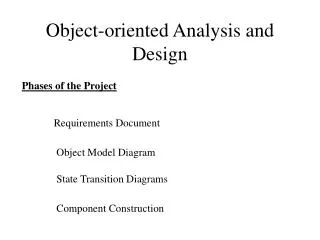
Object-Oriented Analysis Procedure for Object-Oriented Systems Analysis Step 1. Identify the business events and make an event table. Step 2. Identify the use cases and produce a use case diagram for the system. Step 3. Write a use case narrative describing the system’s response to each business event. Step 4. Draw a system sequence diagram for each use case scenario. Step 5. Produce a domain model showing the concepts, attributes, and associations in the problem domain of the system. Step 6. Write a contract for each system operation.
Object-Oriented Design Procedure for Object-Oriented Program Design Step 1. Produce an interaction diagram for each system operation identified during analysis. Step 2. Produce a design class diagram showing the operations from the interaction diagrams. Step 3. Specify the signature and the algorithm for each operation. Step 4. Design the graphical user interface. Step 5. Define the interface to the presentation layer. Step 6. Define the interface to the storage layer. Step 7. Place the classes in packages.
Object-Oriented Deliverables and Outcomes • The ability to tackle more challenging problem domains • Improved communication among users, analysts, designers, and programmers • Increased consistency among analysis, design, and programming activities • Explicit representation of commonality among system components • Robust systems • Reusability of analysis, design, and programming results • Increased consistency among the models developed during object-oriented analysis, design, and programming
The Unified Modeling Language (UML) • A notation that allows the modeler to specify, visualize, and construct the artifacts of software systems, as well as business models • Techniques and notations: • Use cases • Class diagrams • State diagrams • Sequence diagrams • Activity diagrams
Use Cases Revisited • A depiction of a system’s behavior or functionality under various conditions as the system responds to requests from users • Full functioning for a specific business purpose
<<include>> <<extend>> UML Use Case Diagram Symbols Use Case Actor Boundary Connection Include relationship Extend relationship
What is an Actor? • Actor is an external entity that interacts with the system. • Most actors represent user roles, but actors can also be external systems. • An actor is a role, not a specific user; one user may play many roles, and an actor may represent many users.
What is a Boundary? • A boundary is the dividing line between the system and its environment. • Use cases are within the boundary. • Actors are outside of the boundary.
What is a Connection? • A connection is an association between an actor and a use case. • Depicts a usage relationship • Connection does not indicate data flow
What is an <<extend>> Relationship? • A connection between two use cases • Extends a use case by adding new behavior or actions • Specialized use case extends the general use case
What is an <<include>> Relationship? • A connection between two use cases • Indicates a use case that is used (invoked) by another use case • Links to general purpose functions, used by many other use cases
Written Use Cases • Document containing detailed specifications for a use case • Contents can be written as simple text or in a specified format
Object Modeling Using Class Diagrams • Object-oriented approach • Based on Unified Modeling Language (UML) • Features • Objects and classes • Encapsulation of attributes and operations • Polymorphism • Inheritance
Objects • Object: an entity with a well-defined role in an application • Each object has: • State: encompasses the attributes, their values, and relationships of an object • Behavior: represents how an object acts and reacts • Identity: uniqueness, no two objects are the same
Classes • Class: a logical grouping of objects with similar attributes and behaviors • Operation: a function or service provided by all instances of a class • Encapsulation: the technique of hiding internal implementation details of an object from external view
Class Diagram • A diagram showing the static structure of an object-oriented model UML classes are analogous to E-R entities
Types of Operations • Constructor • Creates a new instance of a class • Query • Accesses the state of an object • Update • Alters the state of an object • Scope • Applies to a full class rather than an individual instance
Representing Associations • Association: a relationship among instances of object classes • Association role: the end of an association where it connects to a class • Multiplicity: indicates how many objects participate in a give relationship
UML associations are analogous to E-R relationships. UML multiplicities are analogous to E-R cardinalities.
roles multiplicities Multiplicity notation: 0..10 means minimum of 0 and maximum of 10 1, 2 means can be either 1 or 2 * means any number
Association Class • An association with its own attributes, operations, or relationships UML association classes are analogous to E-R associative entities.
Derived Attributes, Associations, and Roles Derived attributes are calculated based on other attributes Derived items are represented with a slash (/).
Generalization • Superclass-subclass relationships • Subclass inherits attributes, operations, and associations of the superclass • Types of superclasses • Abstract: cannot have any direct instances • Concrete: can have direct instances
Generalization and inheritance implemented via superclass/subclasses in UML, supertypes/subtypes in E-R
Polymorphic Operations • The same operation may apply to two or more classes in different ways • Abstract operations • defined in abstract classes • defined the protocol, but not the implementation of an operation • Methods • the implementation of an operation
Abstraction: Student is an abstract class and calc-tuition() is an abstract operation (italicized) Polymorphism: Here, each type of student has its own version of calc-tuition() Class scope: tuitionPerCred is a class-wide attribute
Aggregation and Composition • Aggregation • A part-of relationship between a component and an aggregate object • Composition • An aggregation in which the part object belongs to only one aggregate object and lives and dies with the aggregate object
Aggregation is represented with open diamonds Composition is represented with filled diamonds
Dynamic Modeling • Representation of activities that occur throughout the lifetime of a system • Types of UML dynamic models • State diagram: state changes within an object • Sequence diagram: time-sequenced interactions between objects • Activity diagram: flow of control between activities within an object
State Diagrams • State • A condition during the life of an object during which it satisfies some conditions, performs some actions or waits for some events • Shown as a rectangle with rounded corners • State Transition • The changes in the attribute of an object or in the links an object has with other objects • Shown as a solid arrow • Diagrammed with a guard condition and action • Event • Something that takes place at a certain point in time, triggering a state transition
Guard condition Action Guard condition A transition is labeled with a guard condition and/or an action, separated with a forward slash / State diagram: a model of the states of a single object and the events that cause the object to change from one state to another
Diagramming Substates and Decomposing States A state can be expanded into substates using nested state diagrams, similar to expansion of processes in different levels of DFDs.
Diagramming Substates and Decomposing States An event can be expanded into using nested state diagrams, and may involve substates and subtransitions and events.
Dynamic Modeling:Sequence Diagrams • A depiction of the interaction among objects during certain periods of time • Elements of a sequence diagram • Objects: represented by boxes at top of diagram • Lifeline: the time during which an object exists • Activation: the time period during which an object performs an operation • Messages: means by which objects communicate with each other
Types of Messages in Sequence Diagrams • Synchronous message • The caller must wait for the receiving object to finish executing the called operation before it can resume execution itself • Asynchronous message • The caller can resume execution right after sending the message, without waiting for the receiver to complete • Simple message • A message that transfers control from the sender to the recipient without describing the details of the communication 20.43
object time lifeline message activation
Process Modeling:Activity Diagrams • Shows the conditional logic for the sequence of system activities needed to accomplish a business process • Clearly shows parallel and alternative behaviors • Can be used to show the logic of a use case
Elements of Activity Diagrams • Activity: a behavior that an object carries out while in a particular state • Transition: a movement from one activity or state to another • Branch: a diamond symbol containing a condition whose results provide transitions to different paths of activities • Synchronization bar: horizontal or vertical bars denoting parallel or concurrent paths of activities • Fork: the beginning of parallel activities • Join: the end of parallel activities • Swimlanes: columns representing different organizatonal units of the system
branch activity synchronization bar swimlane
Analysis Versus Design • Start with existing set of analysis model • Progressively add technical details • Design model must be more detailed than analysis model • Component Diagram • A diagram that shows the software components or modules and their dependencies • Deployment Diagram • A diagram that shows how the software components, process and objects are deployed into the physical architecture of the system
Summary • In this chapter you learned how to: • Define events, state transitions, and sequence diagrams. • Describe concepts and principles of object-orientation. • Describe activities of the different phases of object-oriented development. • Compare object-oriented modeling with traditional systems development approaches. • Develop dynamic models with state, interaction, and activity diagrams. • Model real-world applications with UML.