Download
1 / 30
300 likes | 433 Views
LCLS-II longitudinal space charge (LSC) simulations and sub- fs x-ray pulse generation. Y. Ding, Z. Huang and J. Wu 11.16.2011. outline. LCLS-II LSC check LCLS-II optics: bypass line 250pC, 4.2/13.5 GeV, LH = 20keV 20 pC, 4.2/7/13.5 GeV, LH off sub-fs hard x-ray pulse generation

E N D
LCLS-II longitudinal space charge (LSC) simulations and sub-fs x-ray pulse generation Y. Ding, Z. Huang and J. Wu 11.16.2011
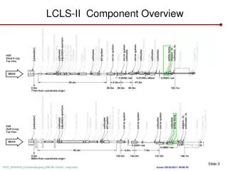
outline • LCLS-II LSC check • LCLS-II optics: bypass line • 250pC, 4.2/13.5 GeV, LH = 20keV • 20 pC, 4.2/7/13.5 GeV, LH off • sub-fs hard x-ray pulse generation • 20 pC, 13.6 GeV, LCLS-I, LH off
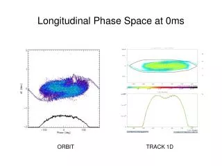
Longitudinal space charge force • LSC results in energy modulation, which will further convert to density modulation (micro-structure), and increase final energy spread . • We used a smooth initial distribution with 10 M particles at 135 MeV, dumped from IMPACT-T simulations. • In Elegant simulations, 250 pC, LSC bin=2000; 20 pC, LSC bin=500. • It is not easy to quantify the LSC effect. We show some LCLS-I simulation examples to compare.
250pC, 13.5 GeV Bypass END LI20 END UND BEG
250pC, 4.2 GeV LI20 END Bypass END UND BEG
A reference from LCLS-I, @ UND BEG 13.6 GeV 4.3 GeV
20 pC, 13.5 GeV, LH off BC2END LI20 END Bypass END UND BEG
20 pC, 13.5GeV, ~ 2kA BC2END UNDBEG
20 pC, 7 GeV, 2 kA LI20END BC2END Bypass END UNDBEG
20 pC, 7 GeV, 2 kA BC2END UNDBEG
20 pC, 4.2 GeV, ~ 2kA, LH off LI20END BC2END UNDBEG Bypass END
20 pC, 4.2GeV, 2kA BC2END UND BEG
Intentionally turn off LSC, 20pC,4.2 GeV BC2 END LI20 END UND BEG
To compare, an example of LCLS-I, 20 pC, 4.3 GeV, LH off @ undulator entrance DL2 R56 = 0 mm @ L3 END DL2 DL2 R56 = 0.13mm FEL works.
If LH can work to increase energy spread to 5 keV… Bypass end UND BEG Slice energy spread for the core part is about 1.4 MeV.
Sub-fs hard x-ray pulse generation “ESASE” without laser modulation
Elegant simulations based on LCLS-I BC2END Initial condition: 20 pC. bunch length=270um rms at OTR2; Energy spread < 1keV rms; Laser heater off. Used 10 M particles in Elelgant. DL2 R56 =0.13 mm.
Check LSC in L3, 20pC, 13.6 GeV UNDBEG L3END DL2 R56 =0.13 mm LSC off in L3 L3END
20pC, DL2 R56 = 0.13mm Wake loss from LSC in undulator Undulator entrance resistive wall wake loss from undulator chamber
LSC induced energy loss • For 20pC DL2=0.13mm case, the LSC wake is much larger that resistive wall wake loss inside undulator. We only include the LSC loss in Genesis simulations. • A chirp is induced in the double horns due to the LSC. At Undulator z=95m, taper = -0.5% over 80m At Undulator entrance
λu x K K z λr z λr How does chirp + negative taper work for FEL? x • FEL works at resonance condition: electrons wiggle one period λu, radiation slips by one wavelength λr. • Small energy chirp with constant undulator K could produce frequency-chirped radiation. • Each slice of the energy chirped bunch will generate radiation at a different frequency along the tapered undulator, and the frequency is equal to the radiation from the slice behind at an previous undulator location. Same frequency radiation will overlap after slippage.
Genesis results, DL2 0.13mm, LSC included in undulator, No taper 60m (HXRSS location) 75m
Genesis results, DL2 0.13mm, LSC included in undulator, taper: -0.2% over 80m 60m 90m 75m
Genesis results, DL2 0.13mm, LSC included in undulator, taper: -0.5% over 80m 60m 90m 75m
Genesis results, DL2 0.13mm, LSC included in undulator, taper: -0.8% over 80m 60m 90m 75m
Genesis results, DL2 0.13mm, LSC included in undulator, taper: -1% over 80m 60m 90m 75m
LCLS-I undulator taper range is good -0.5% over 80m How to test this at LCLS? Using slotted foil, horizontal scan using spectrometer, spoil one of the spikes.
We can also suppress double horns using zero or negative DL2 R56, e.g., for HXRSS DL2, R56 = 0.13mm DL2, R56 = 0.0 @UND BEG @UND BEG
Discussions • LSC should not be a problem for LCLS-II nominal charge (150-250 pC) with laser heater on, but for low charge such as 20 pC with laser heater off, it can affect the bunch temporal profile, especially at very low beam energy; • Laser heater helps to reduce the LSC effects. But for low charge operation, we only need a small heating (about 5 keV), and trickle heating problem prevents working on this low level; • On the other hand, at high energy, we can take advantage of the LSC to fully suppress the beam in the double-horn region, and achieve narrow spikes with very high current, like ESASE; • With the help of a negative undulator taper, it is possible to make the double-horn lase only, hence to produce very short x-ray pulses below fs. It only works at hard x-ray wavelength. This can be tested at LCLS-I. • Longitudinal space charge can be further studied using Impact-z, if needed. Billion particles are preferred.