Download

1 / 34
340 likes | 409 Views
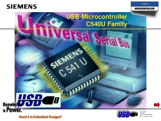
USB-Microcontroller C540U Family. 8 lines. Port 0. Port 1. 6 / 8 lines 1). USB. PLL. 8 lines. Port 2. Transceiver. Module. 8 lines. Port 3. 1) P-LCC-44: 6lines; S-DIP-52: 8lines. SAB-C540U / -C541U Block Diagram. Oscillator Watchdog. RAM 256 x 8.

E N D
8 lines Port 0 Port 1 6 / 8 lines 1) USB PLL 8 lines Port 2 Transceiver Module 8 lines Port 3 1)P-LCC-44: 6lines; S-DIP-52: 8lines SAB-C540U / -C541UBlock Diagram Oscillator Watchdog RAM 256 x 8 OTP4K x 8 (C540U) 8K x 8 (C541U) OSC & Timing C500 EmulationSupport logic(E-Hooks) Prog. Watchdog Timer(C541U only) SSC (SPI) Interface(C541U only) Timer 0 LED Timer 1 LED D+ D- LED Interrupt Unit
SAB-C540U / -C541UList of Features • Enhanced 8-Bit C500-CPU • 500 ns Instruction Cycle Time @ 12 MHz CPU Clock • Two 16-bit Timer/Counters (C501 compatible T0/1) • [4kbytes in the C540U] 8 Kbytes OTP / 256 bytes RAM • USB Device Core (FS/LS speed) • Synchronous Serial Channel, Watchdog Timer [C541U only] • 30 digit. I/O Ports, 32 in SDIP52 • LED Driver capability on 3 dedicated pins, 10 mA / 4,5 to 5,5 V • Power supply voltage range: according to USB spec • Enhanced HooksTechnology • 48 MHz PLL on-chip for FS • Transceiver, D+ D-, on-chip ...the interfacing solution!
Sync SOF Frame# CRC5 EOP USB 00000001 0xA5 0x0DD 0x15 001 Sync DATA0 Sync DATA ACK EOP CRC16 EOP Sync SETUP ADDR ENDP CRC5 EOP 00000001 0xC3 00000001 80 06 00 01 00 00 40 00 0x4B 001 0xBB29 001 00000001 0xB4 0x00 0x0 0x08 001 Device Command: Get descriptor(Who is out there?) Setup stage PC Enumeration process on the C541U
Sync Sync SOF SOF Frame# Frame# CRC5 CRC5 EOP EOP USB 00000001 00000001 0xA5 0xA5 0x0DD 0x0DD 0x15 0x15 001 001 Sync DATA0 Sync DATA ACK EOP CRC16 EOP Sync SETUP ADDR ENDP CRC5 EOP 00000001 0xC3 00000001 80 06 00 01 00 00 40 00 0x4B 001 0xBB29 001 00000001 0xB4 0x00 0x0 0x08 001 Device End of Packet (D+ and D- are low) 5 bit Checksum over Frame# Frame number (0 - 2047)overrolling Start of Frame (every millisecond) Packet start , signaling to the transceiver: “packet arriving“ Start Of Frame...will be generated every millisecond Setup stage PC
Sync SOF Frame# CRC5 EOP USB 00000001 0xA5 0x0DD 0x15 001 Sync DATA0 Sync DATA ACK EOP CRC16 EOP Sync Sync SETUP SETUP ADDR ADDR ENDP ENDP CRC5 CRC5 EOP EOP 00000001 0xC3 00000001 80 06 00 01 00 00 40 00 0x4B 001 0xBB29 001 00000001 00000001 0xB4 0xB4 0x00 0x00 0x0 0x0 0x08 0x08 001 001 Device Endpoint 0 (used for configuration) Address 0 (default addr. f. every new plugged-in dev.) Setup Packet (start of control transfer) Setup packets are fully decoded and Interrupts are generated Setup stage PC Enumeration process on the C541U
USB Sync Sync DATA0 DATA0 Sync DATA DATA ACK EOP CRC16 CRC16 EOP EOP Sync SETUP ADDR ENDP CRC5 EOP 00000001 00000001 0xC3 0xC3 00000001 80 06 00 01 00 00 40 00 80 06 00 01 00 00 40 00 0x4B 001 0xBB29 0xBB29 001 001 00000001 0xB4 0x00 0x0 0x08 001 DATA Device Get device descriptor generates an interrupt Get device descriptor generates an interrupt The Data packet defines what kind of setup transfer is initiated Setup stage PC 80 = transfer direction, std. command 06 = get descriptor 00 = index of descriptor 01 = device descriptor 00 00 = language ID 40 00 = amount of bytes requested by host (little endian format; Lowbyte first, Highbyte least)
Sync SOF Frame# CRC5 EOP USB 00000001 0xA5 0x0DD 0x15 001 Sync DATA0 Sync DATA ACK EOP CRC16 EOP Sync SETUP ADDR ENDP CRC5 EOP 00000001 0xC3 00000001 80 06 00 01 00 00 40 00 0x4B 001 0xBB29 001 00000001 0xB4 0x00 0x0 0x08 001 Device Acknowledge Packet Every control transfer will be ACKnowledged Setup stage PC Enumeration process on the C541U
Sync SOF Frame# CRC5 EOP USB 00000001 0xA5 0x0DE 0x17 001 Sync DATA1 Sync DATA ACK EOP CRC16 EOP Sync ADDR ENDP CRC5 EOP 00000001 0xD2 00000001 12 01 00 01 00 00 00 08 0x4B 001 0xC8E7 001 00000001 0x00 0x0 IN 0x8 001 Device 0x96 Data In Packet (Host requesting data from device) Every data transfer will be initiated with an IN/OUT package by the host(PC) Data stage PC Enumeration process on the C541U
USB Sync Sync DATA1 DATA1 Sync DATA DATA ACK EOP CRC16 CRC16 EOP EOP Sync IN ADDR ENDP CRC5 EOP 00000001 00000001 0xD2 0xD2 00000001 12 01 00 01 00 00 00 08 12 01 00 01 00 00 00 08 0x4B 001 0xC8E7 0xC8E7 001 001 00000001 0x96 0x00 0x0 0x8 001 DATA Device 00 = low-byte of USB-Specification first 8 bytes of the device descriptor initialized in config.h } V 01.00 01 = high-byte of USB-Specification 00 = Device Class 00 = Device Protocol 00 = Device Sub Class 08 = Max. packet size of endpoint 0 Data packages Data stage PC 12 = length of device descriptor 01 = device descriptor type
Sync SOF Frame# Data Out Packet (Host aborts data stage) CRC5 EOP USB 00000001 0xA5 0x0E0 0x0E 001 Sync DATA1 Sync DATA ACK EOP CRC16 EOP Sync ADDR ENDP CRC5 EOP 00000001 0xD2 00000001 0x4B 001 0x0000 001 00000001 0x00 0x0 0x08 001 Device OUT 0x87 Empty data packet indicating data stage end End of Data Stage Data stage Status stage PC Enumeration process on the C541U
USB RESET Device 128160 Reset initiated from host Reset from Host (10ms) PC Enumeration process on the C541U
Sync SOF Frame# CRC5 EOP USB 00000001 0xA5 0x143 0x04 001 Sync DATA0 Sync DATA ACK EOP CRC16 EOP Sync SETUP ADDR ENDP CRC5 EOP 00000001 0xC3 00000001 00 05 02 00 00 00 00 00 0x4B 001 0xD768 001 00000001 0xB4 0x00 0x0 0x08 001 Device DATA Command: Set Address(You are called Number 2 from now on!) PC 00 = direction from host to device, std. command, recipient device 05 = set address 02 = device address nr. 2 00 00 00 00 00 = default this command is handled by the C54x itself without extra software
Sync SOF Frame# CRC5 EOP USB 00000001 0xA5 0x144 0x08 001 Sync DATA1 Sync DATA ACK EOP CRC16 EOP Sync ADDR ENDP CRC5 EOP 00000001 0xD2 00000001 0x4B 001 0x0000 001 00000001 0x00 0x0 0x08 001 Device IN 0x96 Empty data packet from device handled by C54x without Software End of Data Stage Data stage Status stage PC Enumeration process on the C541U
Sync SOF Frame# CRC5 EOP USB 00000001 0xA5 0x151 0x1E 001 Sync DATA0 Sync DATA ACK EOP CRC16 EOP Sync SETUP ADDR ENDP CRC5 EOP 00000001 0xC3 00000001 80 06 00 01 00 00 12 00 0x4B 001 0x072F 001 00000001 0xB4 0x02 0x0 0x15 001 Device Devices is accessed by address 2 Get Descriptor from Device Number 2(What are you like?) Setup stage PC Enumeration process on the C541U
DATA 80 06 00 01 00 00 12 00 Sync SOF Frame# CRC5 EOP USB 00000001 0xA5 0x151 0x1E 001 Sync Sync DATA0 DATA0 Sync DATA ACK EOP CRC16 CRC16 EOP EOP Sync SETUP ADDR ENDP CRC5 EOP 00000001 00000001 0xC3 0xC3 00000001 80 06 00 01 00 00 12 00 0x4B 001 0x072F 0x072F 001 001 00000001 0xB4 0x02 0x0 0x15 001 DATA Device Get Descriptor from Device Number 2(What are you like?), details Setup stage PC 80 = transfer direction, std. command 06 = get descriptor 00 = index of descriptor 01 = device descriptor 00 00 = language ID 12 00 = bytes to transfer
Sync SOF Frame# CRC5 EOP USB 00000001 0xA5 0x152 0x1C 001 Sync DATA1 Sync DATA ACK EOP CRC16 EOP Sync ADDR ENDP CRC5 EOP 00000001 0xD2 00000001 12 01 00 01 00 00 00 08 0x4B 001 0xC8E7 001 00000001 0x02 0x0 IN 0x15 001 Device 0x96 IN request(get data about device description) Data stage PC Enumeration process on the C541U
USB Sync Sync DATA1 DATA1 Sync DATA DATA ACK EOP CRC16 CRC16 EOP EOP Sync IN ADDR ENDP CRC5 EOP 00000001 00000001 0xD2 0xD2 00000001 12 01 00 01 00 00 00 08 12 01 00 01 00 00 00 08 0x4B 001 0xC8E7 0xC8E7 001 001 00000001 0x96 0x02 0x0 0x15 001 DATA Device 00 = lowbyte of USB-Specification first 8 bytes of the device descriptor initialized in config.h 01 = highbyte of USB-Specification 00 = Device Class 00 = Device Sub Class 00 = Device Protocol 08 = Max. packetsize of endpoint 0 IN request, details(get data about device description) Data stage PC 12 = length of device descriptor 01 = device descriptor type
Sync SOF Frame# CRC5 EOP USB 00000001 0xA5 0x153 0x03 001 Sync DATA0 Sync DATA ACK EOP CRC16 EOP Sync ADDR ENDP CRC5 EOP 00000001 0xC3 00000001 8B 05 41 C5 01 00 00 00 0x4B 001 0x86DB 001 00000001 0x02 0x0 IN 0x15 001 Device 0x96 2nd IN request(get data about device description) Data stage PC Enumeration process on the C541U
USB Sync Sync DATA0 DATA0 Sync DATA DATA ACK EOP CRC16 CRC16 EOP EOP Sync IN ADDR ENDP CRC5 EOP 00000001 00000001 0xC3 0xC3 00000001 8B 05 41 C5 01 00 00 00 8B 05 41 C5 01 00 00 00 0x4B 001 0x86DB 0x86DB 001 001 00000001 0x96 0x02 0x0 0x15 001 DATA Device 8B = lowbyte of vendor ID } 05 = highbyte of vendor ID next 8 bytes of the device descriptor initialized in config.h 41 = lowbyte of product ID C5 = highbyte of product ID 2nd IN request, detailsDevice Specific Data are Transferred to PC PC } C541 01 = lowbyte of devicenumber 00 = highbyte of devicenumber 00 = index for manufacturer string descriptor 00 = index for product string descriptor
Sync Sync SOF SOF Frame# Frame# CRC5 CRC5 EOP EOP USB 00000001 00000001 0xA5 0xA5 0x154 0x154 0x1D 0x1D 001 001 Sync Sync DATA1 DATA1 Sync DATA DATA ACK EOP CRC16 CRC16 EOP EOP Sync Sync ADDR ADDR ENDP ENDP CRC5 CRC5 EOP EOP 00000001 00000001 0xD2 0xD2 00000001 00 01 00 01 0x4B 001 0xFCF1 0xFCF1 001 001 00000001 00000001 0x02 0x02 0x0 0x0 0x15 0x15 001 001 Device IN IN 0x96 0x96 DATA 3rd IN requestthe remaining data is transferred Data stage PC 00 = index for serial number string descriptor 01 = number of configurations
Sync SOF Frame# CRC5 EOP USB 00000001 0xA5 0x155 0x02 001 Sync DATA1 Sync DATA ACK EOP CRC16 EOP Sync ADDR ENDP CRC5 EOP 00000001 0xD2 00000001 0x4B 001 0x0000 001 00000001 0x02 0x0 0x15 001 Device OUT 0x87 Command: OUT transfer (with empty data package) finishes the data stage Data stage Status stage PC Enumeration process on the C541U
Sync SOF Frame# CRC5 EOP USB 00000001 0xA5 0x157 0x1F 001 Sync DATA0 Sync DATA ACK EOP CRC16 EOP Sync SETUP ADDR ENDP CRC5 EOP 00000001 0xC3 00000001 80 06 00 02 00 00 FF 00 0x4B 001 0x9725 001 00000001 0xB4 0x02 0x0 0x15 001 Device Command: Get Configuration Descriptor(How does the device function?) Setup stage PC Enumeration process on the C541U
Sync SOF Frame# CRC5 EOP USB 00000001 0xA5 0x157 0x1F 001 Sync Sync DATA0 DATA0 Sync DATA DATA ACK EOP CRC16 CRC16 EOP EOP Sync SETUP ADDR ENDP CRC5 EOP 00000001 00000001 0xC3 0xC3 00000001 80 06 00 02 00 00 FF 00 80 06 00 02 00 00 FF 00 0x4B 001 0x9725 0x9725 001 001 00000001 0xB4 0x02 0x0 0x15 001 DATA Device 00 00 = language ID FF = lowbyte of bytes to transfer 00 = highbyte of bytes to transfer Command: Get Configuration Descriptor(How does the device function?), details PC 80 = transfer direction, std. command 06 = get descriptor 00 = index of descriptor 02 = configuration descriptor
Sync SOF Frame# CRC5 EOP USB 00000001 0xA5 0x158 0x0F 001 Sync DATA1 Sync DATA ACK EOP CRC16 EOP Sync ADDR ENDP CRC5 EOP 00000001 0xD2 00000001 09 02 19 00 01 01 00 60 0x4B 001 0x5020 001 00000001 0x02 0x0 IN 0x15 001 Device 0x96 In Request: Gives Feedback toHow does the device function? Data stage PC Enumeration process on the C541U
USB Sync Sync DATA1 DATA1 Sync DATA DATA ACK EOP CRC16 CRC16 EOP EOP Sync IN ADDR ENDP CRC5 EOP 00000001 00000001 0xD2 0xD2 00000001 09 02 19 00 01 01 00 60 09 02 19 00 01 01 00 60 0x4B 001 0x5020 0x5020 001 001 DATA 00000001 0x96 0x02 0x0 0x15 001 Device first 8 bytes of the device descriptor initialized in config.h In Request: Gives Feedback toHow does the device function?, details PC 09 = length of configuration descriptor 02 = configuration descriptor type 19 00 = length of configuration, interface and endpoint descriptor 01 = number of used interfaces in this configuration 01 = value to set this configuration with SetConfiguration 00 = index to configuration string descriptor 60 = attributes of configuration
Sync SOF Frame# CRC5 EOP USB 00000001 0xA5 0x159 0x10 001 Sync DATA0 Sync DATA ACK EOP CRC16 EOP Sync ADDR ENDP CRC5 EOP 00000001 0xC3 00000001 32 09 04 00 00 01 00 00 0x4B 001 0x273E 001 00000001 0x02 0x0 IN 0x15 001 Device 0x96 2nd In Request: Gives Feedback toHow does the device function? Data stage PC Enumeration process on the C541U
USB Sync Sync DATA0 DATA0 Sync DATA DATA ACK EOP CRC16 CRC16 EOP EOP Sync IN ADDR ENDP CRC5 EOP 00000001 00000001 0xC3 0xC3 00000001 32 09 04 00 00 01 00 00 32 09 04 00 00 01 00 00 0x4B 001 0x273E 0x273E 001 001 DATA 00000001 0x96 0x02 0x0 0x15 001 Device next 8 bytes of the device descriptor initialized in config.h 2nd In Request: Gives Feedback toHow does the device function?, details PC 32 = max. power consumption (in 2mA units) 09 = length of interface descriptor 04 = interface descriptor type 00 = number of interfaces 00 = alternate settings 01 = used endpoints used in this interface 00 = interface class 00 = interface sub class
Sync SOF Frame# CRC5 EOP USB 00000001 0xA5 0x15B 0x0D 001 Sync DATA0 Sync DATA ACK EOP CRC16 EOP Sync ADDR ENDP CRC5 EOP 00000001 0xC3 00000001 00 0x4B 001 0x0000 001 00000001 0x02 0x0 0x15 001 Device IN 0x96 00 = polling interval for interrupt endpoints 3rd In Request: Gives Feedback toHow does the device function?, details PC Enumeration process on the C541U
Sync SOF Frame# CRC5 EOP USB 00000001 0xA5 0x15C 0x15 001 Sync DATA1 Sync DATA ACK EOP CRC16 EOP Sync ADDR ENDP CRC5 EOP 00000001 0xD2 00000001 0x4B 001 0x0000 001 00000001 0x02 0x0 0x15 001 Device OUT 0x87 Command: OUT transferfinishes the data stage Data stage Status stage PC Enumeration process on the C541U
USB Application SupportPhytec KitCON-541 / Starterkit Evaluation Board - Starter Kit Starterkit
detached/attached circuit 5k rev. USB Spec. 1.0 100k 47nF DADD GND n-channel FET 4,0-4,75V 1,5k 3,0-3,6V 0,0 V FULL speed USB driver LOW speed USB driver USB powered / self powered selector C541-Evaluation BoardPhytec KitCON-541 / Starterkit 1 2 3 4 SAB-C541on PGA 44socket D+ D- 96-pol connector female D- D+ Common GND plane USB GND USB Vcc Common Vcc plane USB connector Starterkit
Microcontrollers general: ...for infos on our USB parts Infos on INTERNET http://www.siemens.de/Semiconductor/Microcontroller/ http://www.siemens.de/Semiconductor/products/ICs/34/usb.htm ...the interfacing solution