Download
1 / 17
170 likes | 251 Views
Kennedy Room Cecil Sharp House 2 Regent’s Park Road NW1. Final Exam. 10am Monday, 8 May. lens makers’equation. thin-lens equation. diverging lenses f < 0. converging lenses f > 0. Sign Conventions for Thin Lenses. p > 0 if object is in front of lens (real object)

E N D
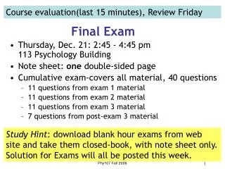
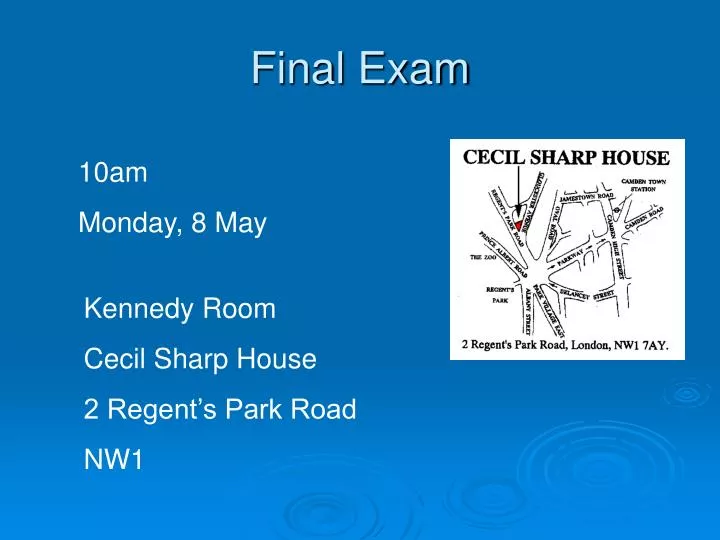
Kennedy Room Cecil Sharp House 2 Regent’s Park Road NW1 Final Exam 10am Monday, 8 May
lens makers’equation thin-lens equation
diverging lenses f < 0 converging lenses f > 0
Sign Conventions for Thin Lenses p > 0 if object is in front of lens (real object) p < 0 if object is in back of lens (virtual object) q > 0 if image is in back of lens (real image) q < 0 if image is in front of lens (virtual image) R1 and R2 > 0 if centre of curvature is in back of lens R1 and R2 < 0 if centre of curvature is in front of lens f > 0 if the lens is converging f < 0 if the lens is diverging
Drawing ray diagrams In drawing ray diagrams, there are three principal rays: (1) one enters parallel to the optical axis and is refracted so as to pass directly or by projection through the second focal point; (2) one passes directly or by projection through the first focal point, and emerges parallel to the optical axis; (3) one passes undeviated through the centre of the lens (where the lens surfaces are locally parallel).
different radii different n
1999 Q4 & 2003 Q6 A thin converging lens could be used to focus the Sun's rays on a sheet of paper with the paper held 50 mm from the lens. a) Sketch a diagram showing how the same lens may be used to form an image of a candle flame on a sheet of paper. b) Will the image of the flame be upright or inverted? c) Where should the lens be placed if the paper is 200 mm from the candle?
2001 Q6 • a) Draw a ray diagram showing the formation of • the image of a slide on a screen by a simple • converging lens. • A thin converging lens of focal length 50 mm is • to be used to form an image of a slide on a • screen 5 m from the lens. • b) How far from the lens should the slide be placed? • If the slide is 24 mm high, how high will the • image be?
2002 Q13 (part) • Draw a ray diagram to show the formation of a real image from a real object by a converging lens. • b) If the focal length of the lens is 20 cm, how far from the lens must the object be placed if the image is to be magnified 10 times?
Q1 2004 a) Draw a ray diagram showing the formation of the image of a slide on a screen by a simple converging lens. A thin converging lens of focal length 50 mm is to be used to form an image of a slide on a screen 5 m from the lens. b) How far from the lens should the slide be placed? c) If the slide is 24 mm high, how high will the image be?
Compute the image distance associated with an object placed 50 cm from the first of two positive lenses. These in turn are separated by 20 cm and have focal lengths of 30 cm and 50 cm, respectively. Also, find the overall magnification for this system.
Q10 2005 a) Describe two types of image aberrations. State, with reason, whether they occur with mirrors, lenses or both, and explain how they might be corrected. An object 1.2 cm high is placed 4 cm from a double convex lens with a focal length of 12 cm. b) Locate the image. c) Is the image real or virtual? Why? A second lens of focal length +6 cm is placed 12 cm to the right of the lens above. d) Calculate the position of the final image. e) Draw a ray diagram, tracing the rays from the original object to the final image. f) What is the overall magnification of this combination of lenses?
2003 Q9 a) Describe two types of lens aberrations and how they might be corrected. On a table, a 3-cm tall candle sits 12 cm to the left of a bi-convex thin lens of focal length 9 cm, which in turn is 21 cm to the left of a bi-concave thin lens of focal length -18 cm. b) Locate the image formed by the system. c) What is the magnification of the image formed by the system? d) Is the image formed by the system real or virtual? Why? e) Is the image formed by the system erect or inverted? Why? The above compound lens is placed so that its negative back lens is 60 cm away from the vertex of a convex spherical mirror having a 15-cm radius. f) What is the final position of the image formed by the lens-mirror system of the candle in the same position as before? g) What is the size of the final image? h) Is the final image virtual or real? Why? i) Is the final image erect or inverted? Why?