Download
1 / 21
210 likes | 283 Views
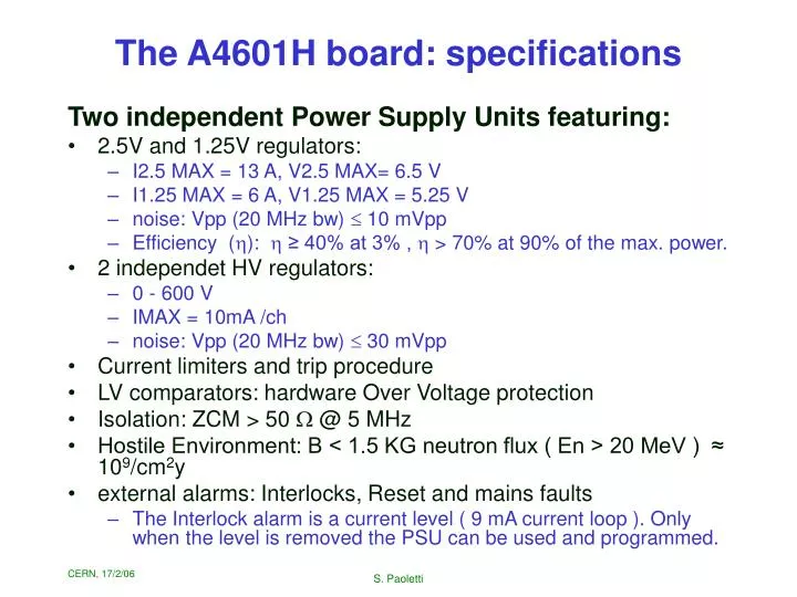
The A4601H board: specifications. Two independent Power Supply Units featuring: 2.5V and 1.25V regulators: I2.5 MAX = 13 A, V2.5 MAX= 6.5 V I1.25 MAX = 6 A, V1.25 MAX = 5.25 V noise: Vpp (20 MHz bw) 10 mVpp Efficiency ( h ): h ≥ 40% at 3% , h > 70% at 90% of the max. power.

E N D
The A4601H board: specifications Two independent Power Supply Units featuring: • 2.5V and 1.25V regulators: • I2.5 MAX = 13 A, V2.5 MAX= 6.5 V • I1.25 MAX = 6 A, V1.25 MAX = 5.25 V • noise: Vpp (20 MHz bw) 10 mVpp • Efficiency (h): h ≥ 40% at 3% , h > 70% at 90% of the max. power. • 2 independet HV regulators: • 0 - 600 V • IMAX = 10mA /ch • noise: Vpp (20 MHz bw) 30 mVpp • Current limiters and trip procedure • LV comparators: hardware Over Voltage protection • Isolation: ZCM > 50 W @ 5 MHz • Hostile Environment: B < 1.5 KG neutron flux ( En > 20 MeV ) ≈ 109/cm2y • external alarms: Interlocks, Reset and mains faults • The Interlock alarm is a current level ( 9 mA current loop ). Only when the level is removed the PSU can be used and programmed. S. Paoletti
The PS system evolution(my point of view) • Power supplies are detector components • The past year brought to us: • first fully integrated complex detector structures • “H” type power supplies • The R&D was performed by Florence (G. Parrini) according to the original scheme, with “F” power supplies • CMS decided to go into UXC. First “H” power supplies then were available since Summer 2005. • Needs of integration centers were first satisfied: Florence got one new crate and few “H” power supplies only in fall 2005 • Complex detector structures brought us more understanding of: • some noise and oscillation issues • grounding scheme • interlocks S. Paoletti
The PS system evolution(my point of view) • There are (of course) some implications also for the PS system • Some issues were identified and recently Florence studied with CAEN how to address them: • Grounding (lateral plates, back boards, crates) • Firmware upgrade (branch controller) • 600 Hz oscillation • ramp up / ramp down behavior • Changes on the power supply system (not only PSMs) should be addressed in a coordinated way. Any non agreed “experimenting” on PSMs and crates is going to increase entropy, duplicate the work, jeopardize the activity • Florence is the technical contact for the power supplies • Florence has to take part in any technical discussion with CAEN S. Paoletti
Grounding • Recently agreed with CAEN which is the most effective method to ground the PSMs and the backboards • We defined the scheme which brings to ground front panels, lateral plates, back boards: • The reference ground is the crate (LAB ground) • The 48V RTN is to be connected to the same ground (but on a separate path) S. Paoletti
48 Vp RTN +48 Vp GND to PSMs earth Al rails • Also the scheme to ground the crate was fixed: • get rid of lousy ground wires S. Paoletti
Firmware upgrades • Let’s be prepared: there will be periodical firmware upgrades • The same line of models (EASY) regards many different detectors • The most recent upgrade: • branch controller firmware upgrade (could not see more than 15 boards on the same branch) • Other upgrades foreseen: • A4602 • A4601 (asked to transform a long UNV in permanent alarm) S. Paoletti
600 Hz oscillations • The time response of the sensing loop used to be (by design) O(0.5 ms) • It was clear from the beginning that the sensing loop had to be tuned on realistic loads, with final cables • In September 2005 CAEN intervention on TOB rods was required: • they had instabilities • it was decided to relax the timing of the sensing loop O(1 ms). • The latest “F” type PSMs where tuned on TOB ! • The same scheme was adopted for “H” type PSUs • This year (end of October) TOB reported 600 Hz oscillations • Are they due to the different PSU model ? • Something changed in the rod impedances ? • LIC cables were now used (in place of MSC) ? • Oscillations can be measured with a scope at the output connector • Not all PSMs showed the oscillations S. Paoletti
600 Hz oscillations • CAEN intervention speeded up again the sensing loop in all PSMs at 186. • Florence was not informed in advance of the intervention • missed one opportunity: cannot anymore compare “good” and “bad” PSMs • TIB (Florence structure) did not observe this kind of oscillations • TIB (Pisa): study is going on. If any, the effect has to be quite tiny wrt TOB observations. • TEC now reports this kind of oscillations • Florence (again) was not informed • We came to know this only by CAEN S. Paoletti
ON/OFF behavior • I recently tested the Florence A4601H performance (ICM, ZCM, …) • I found a problem when powering the LV cannels with very high current loads. • For I2.5 > 7.5 A the 1.25 would not raise • Never observed with “F” type boards I2.5=10A I1.25=0A • CAEN introduced a change: • if any of the LV channels is not reaching a Vthr value (~ 0.5 V) the sensing loop of that channel will not start • this feature was introduced in order to protect from accidental wrong sense connection on the detector structure • Not all A4601H have this feature introduced: we now have the IDs of A4601H not affected by this feature S. Paoletti
ON/OFF behavior The solution: • lower the Vthr to ~0.3 V • change synchronization and equalize the speeds of 2.5 and 1.25 ramps I2.5=10A I1.25=0A S. Paoletti
I2.5=10A I1.25=0A I2.5=10A I1.25=0A ON/OFF behavior • Another problem spotted: • the 2.5V turn-OFF is too quick • this can cause over voltages on the 1.25 V @ high I2.5 • Solution • slow down the 2.5 ramp S. Paoletti
Interlocks • (I leave this to Machi) S. Paoletti
The “service pack 1” • Changes to be performed on A4601H: • grounding • ON/OFF ramps • 600 Hz capacitor • Interlocks ? • Desirable to implement them in one step “service pack 1” • Grounding and ON/OFF ramps are “sound” modifications: they are being implemented (already since January) to the rest of the A4601H and crate production • We’d like to experiment the 600Hz capacitor on TIB structures before accepting it as a “universal” modification. • have also to check that it does not interfere with the LV ramp corrections • I arranged for having upgraded boards (with all corrections implemented) quickly: • boards are now ready in Pisa to be tested on TIB structure S. Paoletti
The “Service Pack 1” • After the modifications will be “certified” on the TIB structure, we will be ready to implement the upgrade to all the PSM production. • DB essential: • serial number • movements • problems encountered • firmware version • hardware revisions/interventions • Please be disciplined: communicate all data to Horst. S. Paoletti
Further Remarks S. Paoletti
48 V • We need a CMS-tracker contact for the 48V • We need equipment: • certified by quality assurance • with proper electrical characterization • The system foresees a 48Vs independent of the 48Vp and backed up for O(100 sec) • the 48Vs has to be foreseen • the system is not foreseen to work without 48Vs • contradictory information should not be spread around S. Paoletti
Power Consumption and Heat Dissipation • G. Parrini first made the calculation of the power demand and heat dissipation on racks • I updated those calculations two times (according to variations on the known cable lengths) • http://hep.fi.infn.it/CMS/power/power_files/psu/FE_power_2.pdf • There are important discrepancies wrt numbers currently used for crate and rack dimensioning • I raised the point several times • I got no reply, I got no further news about the racks • discrepancies mainly due to: • bad knowledge of PSU efficiency curves and power consumption • bad knowledge of cable resistances • different considerations on the “safety margin” to be applied on top of the standard consumption S. Paoletti
Power Consumption and Heat Dissipation July 2005, talk by Shabbir Akhtar S. Paoletti
Cabling and racks distribution • power supplies • cables • DCS • Florence is committed in all of these items • Good (bi-directional) communications should be kept in order to reach the goal. S. Paoletti
DCS • Florence made important contributions to the control system of the power supplies (see R.Chierici’s talk July 2005) • first implementation of A4601 into JCOP • first working FSM • We intend to keep the involvement into ps-related DCS tasks and to take part to the decisions: • control of PS • FSM • PS safety issues • Main activities are now going to be CERN-centered (discussions, test stations, MTCC) • We should find a way to collaborate and assure a proper flow of the information • Weekly VRVS meeting will be established S. Paoletti
Link with CMS infrastructure • Flow of information to be improved here • Interface with A.Herve` for PSU and cable issues to be defined What does it mean: we don’t have any local ground connection ? Was this configuration ever discussed ? S. Paoletti