Download
1 / 49
520 likes | 760 Views
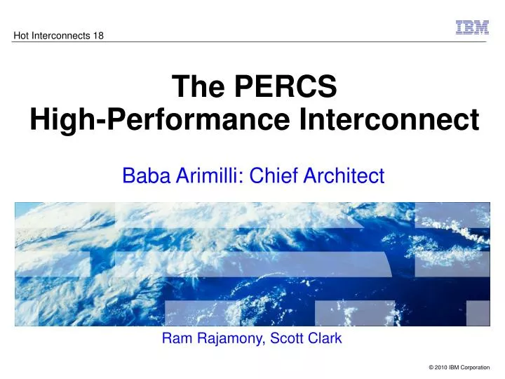
Hot Interconnects 18. The PERCS High-Performance Interconnect. Baba Arimilli: Chief Architect. Ram Rajamony, Scott Clark. Outline. HPCS Program Background and Goals PERCS Topology POWER7 Hub Chip Overview HFI and Packet Flows ISR and Routing CAU Chip and Module Metrics Summary.

E N D
Hot Interconnects 18 The PERCS High-Performance Interconnect • Baba Arimilli: Chief Architect Ram Rajamony, Scott Clark
Outline • HPCS Program Background and Goals • PERCS Topology • POWER7 Hub Chip • Overview • HFI and Packet Flows • ISR and Routing • CAU • Chip and Module Metrics • Summary “This design represents a tremendous increase in the use of optics in systems, and a disruptive transition from datacom- to computercom-style optical interconnect technologies.” This material is based upon work supported by the Defense Advanced Research Projects Agency under its Agreement No. HR0011-07-9-0002. Any opinions, findings and conclusions or recommendations expressed in this material are those of the author(s) and do not necessarily reflect the views of the Defense Advanced Research Projects Agency.
DARPA’s “High Productivity Computing Systems” Program Goal: Provide a new generation of economically viable high productivity computing systems for the national security and industrial user community • Impact: • Performance (time-to-solution): speedup by 10X to 40X • Programmability (idea-to-first-solution): dramatically reduce cost & development time • Portability (transparency): insulate software from system • Robustness (reliability): continue operating in the presence of localized hardware failure, contain the impact of software defects, & minimize likelihood of operator error • Applications: Nuclear Stockpile Stewardship Climate Modeling Weapons Integration Ship Design Weather Prediction Ocean/wave Forecasting PERCS – Productive, Easy-to-use, Reliable Computing System is IBM’s response to DARPA’s HPCS Program
What The HPC Community Told Us They Needed Maximum Core Performance … to minimize number of cores needed for a given level of performance as well as lessen the impact of sections of code with limited scalability Low Latency, High Bandwidth Communications Fabric … to maximize scalability of science and engineering applications Large, Low Latency, High Bandwidth Memory Subsystem … to enable the solution of memory-intensive problems Large Capacity, High Bandwidth I/O Subsystem … to enable the solution of data-intensive problems Reliable Operation … to enable long-running simulations 5
Design Goals • High bisection bandwidth • Low packet latency • High interconnect bandwidth (even for packets < 50 bytes)
Design Goals • High bisection bandwidth • Small fanout from hub chip necessitates mesh/toroidal topologies • Use very high fanout from hub chip to increase interconnect “reach” • Low packet latency • Large number of stages requires delays at every stage • Use a topology with very small number of hops • High interconnect bandwidth (even for packets < 50 bytes) • Architect switch pipeline to handle small packets • Automatically (in hardware) aggregate and disaggregate small packets
End Result: The PERCS System Rack Bulk Power Regulators Universal Power Input Storage Enclosure Hub Chip Module POWER7 QCM Water Conditioning Units Accepts Standard Building Chilled Water
Topology • Numerous Topologies evaluated • Converged on a Multi-level Direct Connect Topology to addresses the design goals of high bisection bandwidth and low latency • Multiple levels • All elements in each level of the hierarchy are fully connected with each other • Examples:
Design Trade-offs • Narrowed options to 2-level and 3-level direct-connect topologies • Link bandwidth ratios determined by the number of levels • Let the levels be denoted using Z, L, D • 3 levels: longest direct path is ZLZ-D-ZLZ need Z:L:D bandwidth ratios at 4:2:1 • 2 levels: longest direct path is L-D-L need L:D bandwidth ratios at 2:1 • Maximum system size determined by the numbers of links of each type • 3 levels: Maximum system size is ~ Z4.L2.D1 .Number-of-POWER7s-per-Hub chip • 2 levels: Maximum system size is ~ L2.D1 .Number-of-POWER7s-per-Hub chip
Too many Hub chips high cost Too much bandwidth per link high power Too many links low point-to-point bw, high cost & power Design Trade-offs within the Topology • Aggregate bi-directional link bandwidths (in GB/s) • 3 levels, 1 POWER7/Hub chip: 4-2-8 D = 40 L = 80 Z = 160 • 3 levels, 2 POWER7s/Hub chip: 2-2-8 D = 80 L = 160 Z = 320 • 3 levels, 4 POWER7s/Hub chip: 4-1-8 D = 160 L = 320 Z = 640 • 2 levels, 1 POWER7/Hub chip: 64-32 D = 40 L = 80 • 2 levels, 2 POWER7s/Hub chip: 32-32 D = 80 L = 160 • 2 levels, 4 POWER7s/Hub chip: 16-32 D = 160 L = 320 • 2 levels, 4 POWER7s/Hub chip: 64-16 D = 160 L = 320 • 2 levels, 4 POWER7s/Hub chip: 4-64 D = 160 L = 320 • … • 2 levels, 4 POWER7s/Hub chip: 16-32 D = 160 L = 320 design point
PERCS POWER7 Hierarchical Structure • POWER7 Chip • 8 Cores • POWER7 QCM & Hub Chips • QCM: 4 POWER7 Chips • 32 Core SMP Image • Hub Chip: One per QCM • Interconnect QCM, Nodes, and Super Nodes • Hub Module: Hub Chip with Optics • POWER7 HPC Node • 2U Node • 8 QCMs, 8 Hub Chip Modules • 256 Cores • POWER7 ‘Super Node’ • Multiple Nodes per ‘Super Node’ • Basic building block • Full System • Multiple ‘Super Nodes’ Hub Chip Hub Module with Optics
Supernode full direct connectivitybetween Quad Modulesvia L-links Drawer Quad POWER7 module Hub chip POWER7 Coherency Bus HFI (Host Fabric Interface) ISR (Integrated Switch/ Router) SmpRouter POWER7 chip “local” L-links within Drawers 1 7 POWER7 chip 1 Full direct Connectivitybetween Supernodes via D-links CAU (Collective Acceleration Unit POWER7 chip “remote” L-links between Drawers . 24 . . HFI (Host Fabric Interface) 1 POWER7 chip 16 D-links 8 N n . . 1 . 1 1 Logical View of PERCS Interconnect . . .
System-Level D-Link Cabling Topology • Number of SuperNodes in system dictates D-link connection topology • >256 SN Topology: 1 D-link interconnecting each SN-SN pair • 256-SN Topology: 2 D-Links interconnecting each SN-SN pair • 128-SN Topology: 4 D-links interconnecting each SN-SN pair • 64-SN Topology: 8 D-links interconnecting each SN-SN pair • 32-SN Topology: 16 D-links interconnecting each SN-SN pair • 16-SN Topology: 32 D-links interconnecting each SN-SN pair
P7 P7 P7 P7 Coherency Bus Ctl HFI Hub HFI Hub CAU Integrated Switch Router POWER7 Hub Chip Overview • Extends POWER7 capability for high performance cluster optimized systems • Replaces external switching and routing functions in prior networks • Low diameter Two-tier Direct graph network topology is used to interconnect tens of thousands of POWER7 8-core processor chips to dramatically improve bi-section bandwidth and latency • Highly Integrated Design • Integrated Switch/Router (ISR) • Integrated HCA (HFI) • Integrated MMU (NMMU) • Integrated PCIe channel controllers • Distributed function across the POWER7 and Hub chipset • Chip and optical interconnect on module • Enables maximum packaging density • Hardware Acceleration of key functions • Collective Acceleration • No CPU overhead at each intermediate stage of the spanning tree • Global Shared Memory • No CPU overhead for remote atomic updates • No CPU overhead at each intermediate stage for small packet disaggregation/aggregation • Virtual RDMA • No CPU overhead for address translation
POWER7 LinkCtl POWER7 Coherency Bus HFI NMMU HFI PCIE 2.1 x16 LL LinkCtl CAU PCIE 2.1 x16 ISR PCIE 2.1 x8 24x 16x LR LinkCtl D LinkCtl 24x 16x POWER7 Hub Chip Block Diagram POWER7 QCM Connect 192 GB/s 4 POWER7 Links – 3 Gb/s x 8B 336 GB/s 40 GB/s Inter-Node Connect 7 LLocal – 3 Gb/s x 8B PCIE Connect 3 PCIE – 5 Gb/s x 40b 24 LRemote – 10 Gb/s x 6b 16 D – 10 Gb/s x 12b Intra-SuperNode Connect Inter-SuperNode Connect 240 GB/s 320 GB/s 1.128 TB/s of off-chip interconnect bandwidth
POWER7 LinkCtl POWER7 Coherency Bus HFI NMMU HFI PCIE 2.1 x16 LL LinkCtl CAU PCIE 2.1 x16 ISR PCIE 2.1 x8 24x 16x LR LinkCtl D LinkCtl 16x 24x Host Fabric Interface (HFI) Features • Non-coherent interface between the POWER7 QCM and the ISR • Four ramps/ports from each HFI to the ISR • Communication controlled through “windows” • Multiple supported per HFI • Address Translation provided by NMMU • HFI provides EA, LPID, Key, Protection Domain • Multiple page sizes supported • POWER7 Cache-based sourcing to HFI, injection from HFI • HFI can extract produced data directly from processor cache • HFI can inject incoming data directly into processor L3 cache
Host Fabric Interface (HFI) Features (cont’d) • Supports three APIs • Message Passing Interface (MPI) • Global Shared Memory (GSM) • Support for active messaging in HFI (and POWER7 Memory Controller) • Internet Protocol (IP) • Supports five primary packet formats • Immediate Send • ICSWX instruction for low latency • FIFO Send/Receive • One to sixteen cache lines moved from local send FIFO to remote receive FIFO • IP • IP to/from FIFO • IP with Scatter/Gather Descriptors • GSM/RDMA • Hardware and software reliability modes • Collective: Reduce, Multi-cast, Acknowledge, Retransmit
Host Fabric Interface (HFI) Features (cont’d) • GSM/RDMA Packet Formats • Full RDMA (memory to memory) • Write, Read, Fence, Completion • Large message sizes with multiple packets per message • Half-RDMA (memory to/from receive/send FIFO) • Write, Read, Completion • Single packet per message • Small-RDMA (FIFO to memory) • Atomic updates • ADD, AND, OR, XOR, and Cmp & Swap with and without Data Fetch • Remote Atomic Update (FIFO to memory) • Multiple independent remote atomic updates • ADD, AND, OR, XOR • Hardware guaranteed reliability mode
HFI Window Structure Real (physical) memory HFI Window Context Detail Window 0 HFI command count, … Send FIFO address Window 2 send FIFO Window 1 Receive FIFO address Window 2 rcv FIFO Window 2 Segment table for task using window 2 Epoch vector address SDR1 Page table pointer Page table for partition using window 2 Job key Process ID LPAR ID Window n USER OS Hypervisor
End-to-End Packet Flow . Proc, caches Proc, caches Mem Proc, caches Proc, caches Mem ... ... POWER7 Chip POWER7 Chip POWER7 Coherency Bus POWER7 Coherency Bus POWER7 Link POWER7 Link POWER7 Coherency Bus POWER7 Coherency Bus HubChip HubChip HFI HFI HFI HFI ISR ISR ISR ISR ISR Network .
HFI FIFO Send/Receive Packet Flow Check Space in SFIFO Calculate flits count • Single or Multiple packets per doorbell • Packets processed in FIFO order • Packet sizes up to 2KB • Bandwidth optimized Get send FIFO slots Build base header and message header User callback to consume the data Copy data to send FIFO Copy from recv FIFO to user’s buffer Ring HFI doorbell Recv FIFO (Cache/Memory) yes Send FIFO (Cache/Memory) Packet is valid dma_read ISR NETWORK HFI HFI dma_write of packet read_data Source Node Destination Node
HFI Immediate Send/Receive Packet Flow • Single cache line packet size • Latency optimized Check for available HFI Buffers User callback to consume the data Build base header and message header in Cache Copy from recv FIFO to user’s buffer Execute ICSWX instruction Recv FIFO (Cache/Memory) yes Packet is valid Cache ISR NETWORK HFI HFI push of data dma_write of packet Source Node Destination Node
HFI GSM/RDMA Message Flow (RDMA Write) Check Space in RDMA CMD FIFO Build RDMA base header in RDMA CMD FIFO • Single or Multiple RDMA messages per doorbell • Send-side HFI breaks a large message into multiple packets of up to 2KB each • Large RDMA messages are interleaved with smaller RDMA messages to prevent HOL blocking in the RDMA CMD FIFO • Initiator notification packet traverses network in opposite direction from data (not shown) Ring HFI doorbell RDMA CMD FIFO (Cache/Memory) User call back to consume notification dma_read RDMA_HDR Memory Memory Task EA Space Generate initiator and/or remote completion notifications to receive FIFOs for last packet dma_read RDMA Payload Task EA Space ISR NETWORK HFI HFI dma_write of packet Source Node Destination Node
HFI GSM Small RDMA (Atomic) Update Flow Check Space in SFIFO Calculate flits count • Single or Multiple packets per doorbell • Packets processed in FIFO order • Single cache line packet size • Initiator notification packet traverses network in opposite direction from data (not shown) Get send FIFO slots Build base header and message header Copy data to send FIFO User call back to consume notification Ring HFI doorbell Memory Send FIFO (Cache/Memory) Generate initiator and/or remote completion notifications to receive FIFOs with or without Fetch Data Atomic RMW Task EA Space dma_read ISR NETWORK HFI HFI dma_write of packet read_data Source Node Destination Node
HFI GSM Remote Atomic Update Flow Check Space in SFIFO Calculate flits count • Single or Multiple packets per doorbell • Packets processed in FIFO order • Single cache line packet size • Single or multiple remote atomic updates per packet • No notification packets • Assumes Hardware reliability Get send FIFO slots Build base header and message header Copy data to send FIFO Ring HFI doorbell Update packet sent indicated count register Memory Send FIFO (Cache/ Memory) Atomic RMW Task EA Space Update packet received indicated count register dma_read ISR NETWORK HFI HFI dma_write of packet read_data Source Node Destination Node
POWER7 LinkCtl POWER7 Coherency Bus HFI NMMU HFI PCIE 2.1 x16 LL LinkCtl CAU PCIE 2.1 x16 ISR PCIE 2.1 x8 24x 16x LR LinkCtl D LinkCtl 16x 24x Integrated Switch Router (ISR) Features • Two tier, full graph network • 3.0 GHz internal 56x56 crossbar switch • 8 HFI, 7 LL, 24 LR, 16 D, and SRV ports • Virtual channels for deadlock prevention • Input/Output Buffering • 2 KB maximum packet size • 128B FLIT size • Link Reliability • CRC based link-level retry • Lane steering for failed links • IP Multicast Support • Multicast route tables per ISR for replicating and forwarding multicast packets • Global Counter Support • ISR compensates for link latencies as counter information is propagated • HW synchronization with Network Management setup and maintenance
Integrated Switch Router (ISR) - Routing • Packet’s View: Distributed Source Routing • The paths taken by packets is deterministic direct routing • The packets are injected with the desired destination indicated in the header • Partial Routes are picked up in the ISR at each hop of the path • Routing Characteristics • 3-hop L-D-L longest direct route • 5-hop L-D-L-D-L longest indirect route • Cut-through Wormhole routing • Full hardware routing using distributed route tables across the ISRs • Source route tables for packets injected by the HFI • Port route tables for packets at each hop in the network • Separate tables for inter-supernode and intra-supernode routes • FLITs of a packet arrive in order, packets of a message can arrive out of order
Integrated Switch Router (ISR) – Routing (cont’d) • Routing Modes • Hardware Single Direct Routing • Hardware Multiple Direct Routing • For less than full-up system where more than one direct path exists • Hardware Indirect Routing for data striping and failover • Round-Robin, Random • Software controlled indirect routing through hardware route tables • Route Mode Selection • Dynamic network information provided to upper layers of the stack to select route mode • Decision on route can be made at any layer and percolated down • Route mode is placed into the packet header when a packet is injected into the ISR
SuperNode Hub chip with Integrated Switch Router (ISR) QCM: 4 chip POWER7 processor module POWER7 IH Drawer with 8 octants (QCM-Hub chip pairs) 7 Llocal Links to Hubs within the drawer 16 D links to other supernodes ISR 24 Lremote Links to Hubs in other three drawers of the supernode
Direct Routing SuperNode B SuperNode A SN-SN Direct Routing L-Hops: 2 D-Hops: 1 Total: 3 hops LR12 LR21 D3 • Max Bisection BW • One to many paths depending on system size
Indirect Routing SuperNode B SuperNode x SuperNode A SN-SN Indirect Routing L-Hops: 3 D-Hops: 2 Total: 5 hops LL7 Total paths = # SNs – 2 LR21 D5 D12 LR30
Integrated Switch Router (ISR) – Network Management • Network Management software initializes and monitors the interconnect • Central Network Manager (CNM) runs on the Executive Management Server (EMS) • Local Network Management Controllers (LNMC) run on the service processors in each drawer • Cluster network configuration and verification tools for use at cluster installation • Initializes the ISR links and sets up the route tables for data transmission • Runtime monitoring of network hardware • Adjusts data paths to circumvent faults and calls out network problems • Collects state and performance data from the HFI & ISR on the hubs during runtime • Configures and maintains Global Counter master
POWER7 LinkCtl POWER7 Coherency Bus HFI NMMU HFI PCIE 2.1 x16 LL LinkCtl CAU PCIE 2.1 x16 ISR PCIE 2.1 x8 24x 16x LR LinkCtl D LinkCtl 16x 24x Collectives Acceleration Unit (CAU) Features • Operations • Reduce: NOP, SUM, MIN, MAX, OR, AND, XOR • Multicast • Operand Sizes and Formats • Single Precision and Double Precision • Signed and Unsigned • Fixed Point and Floating Point • Extended Coverage with Software Aid • Types: barrier, all-reduce • Reduce ops: MIN_LOC, MAX_LOC, (floating point) PROD • Tree Topology • Multiple entry CAM per CAU: supports multiple independent trees • Multiple neighbors per CAU: each neighbor can be either a local or remote CAU/HFI • Each tree has one and only one participating HFI window on any involved node • It’s up to the software to setup the topology
Collectives Acceleration Unit (CAU) Features (cont’d) • Sequence Numbers for Reliability and Pipelining • Software driven retransmission protocol if credit return is delayed • The previous collective is saved on CAU for retransmission • Allows retransmit from point of failure vs. restart of entire operation • Reproducibility • Binary trees for reproducibility • Wider trees for better performance
CAU: Example of Trees Tree A: node 0, 1, 2, 3 Tree B: node 0, 5 Tree C: node 4, 5, 6, 7 Tree D: node 3, 7 B HFI CAU HFI CAU Node 0 Node 4 Node 1 Node 5 HFI CAU HFI CAU C A Node 2 Node 6 HFI CAU HFI CAU D Node 3 Node 7 HFI CAU HFI CAU
CAU: Operations on A Tree Broadcast Reduce HFI CAU Node 4 HFI CAU Node 4 Node 5 Node 5 Root HFI CAU HFI CAU Node 6 Node 6 Root HFI CAU HFI CAU Node 7 Node 7 HFI CAU HFI CAU
POWER7 Hub Chip POWER7 Phys PCIE Phys PCIE PCIE PCIE LR & DLinkPhys • 45 nm lithography, Cu, SOI • 13 levels metal • 440M transistors • 582 mm2 • 26.7 mm x 21.8 mm • 3707 signal I/O • 11,328 total I/O • 61 mm x 96 mm Glass Ceramic LGA module • 56 – 12X optical modules • LGA attach onto substrate • 1.128 TB/s interconnect bandwidth CAU POWER7 Coherency Bus D LinkPhys HFI NMMU HFI ISR POWER7 Phys POWER7 Coherency Bus LLocal Link Phys
Off-chip Interconnect and PLL’s 1.128 TB/s Total Hub I/O Bandwidth • (4) 8B W,X,Y,Z Interconnect Bus to POWER7 • 3.0 Gb/s Single Ended EI-3 →192 GB/s throughput • (7) 8B L-Local (LL) Interconnect Busses to Hub chips • 3.0 Gb/s Single Ended EI-3 →336 GB/s throughput • Shared physical transport for Cluster Interconnect andPOWER7 Coherency Bus protocol • (24) L-Remote: LR[0..23] within Drawer Hub Optical Interconnect Bus • 6b @ 10Gb/s Differential, 8/10 encoded →240GB/s throughput • (16) D[0..15] between Drawer Hub Optical Interconnect Bus • 10b @ 10Gb/s Differential 8/10 encoded →320 GB/s throughput • PCI General Purpose I/O →40GB/s throughput • 24 total PLL’s • (3) “Core” PLLs • (1) Internal Logic • (1) W,X,Y,Z EI3 buses • (1) LL0 – LL6 EI3 buses • (2) ”Intermediate Frequency “IF LC Tank” PLLs • (1) Optical LR buses • (1) Optical D buses • (14) High Frequency “HF LC Tank” PLLs • (6) Optical LR buses • (8) Optical D buses • (5) PCI-E “Combo PHY” PLLs
Optical Modules & Fiber Ribbons mLGA Interposer Hub Module Overview Module Assembly D-link Optical Module Sites POWER7 Hub Chip Heat Spreader POWER7 Hub Chip LR-link Optical Module Sites
Key System Benefits Enabled by the PERCS Interconnect • A PetaScale System with Global Shared Memory • Dramatic improvement in Performance and Sustained Performance • Scale Out Application Performance (Sockets, MPI, GSM) • Ultra-low latency, enormous bandwidth and very low CPU utilization • Elimination of the Traditional Infrastructure • HPC Network: No HCAs and External Switches, 50% less PHYs and cables of equivalent fat-tree structure with the same bisection bandwidth • Storage: No FCS HBAs, External Switches, Storage Controllers, DASD within the compute node • I/O: No External PCI-Express Controllers • Dramatic cost reduction • Reduce the overall Bill of Material (BOM) costs in the System • A step function improvement in Data Center reliability • Compared to commodity clusters with external storage controllers, routers/switches, etc. • Full virtualization of all hardware in the data center • Robust end-to-end systems management • Dramatic reduction in Data Center power compared to commodity clusters
Acknowledgements • Authors • Baba Arimilli, Ravi Arimilli, Robert Blackmore, Vicente Chung , Scott Clark, Wolfgang Denzel, Ben Drerup, Torsten Hoefler, Jody Joyner, Jerry Lewis , Jian Li, Nan Ni, Ram Rajamony, Aruna Ramanan and Hanhong Xue This material is based upon work supported by the Defense Advanced Research Projects Agency under its Agreement No. HR0011-07-9-0002. Any opinions, findings and conclusions or recommendations expressed in this material are those of the author(s) and do not necessarily reflect the views of the Defense Advanced Research Projects Agency.