Download
1 / 34
340 likes | 454 Views
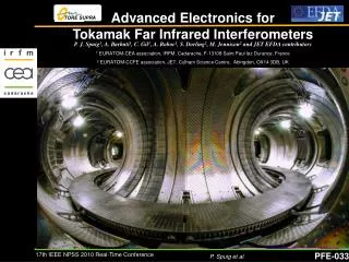
EFTS/EODI Training week 12 th June 2009. Far Infrared diagnostics for fusion plasma experiments Alexandru Boboc EFDA-JET, UKAEA, Culham Science Centre, Abingdon, Oxfordshire, OX14 3DB, UK. OUTLINE. Principle of interferometry/polarimetry Why a FIR plasma diagnostic ?

E N D
EFTS/EODI Training week 12th June 2009 • Far Infrared diagnostics for fusion plasma experiments • Alexandru Boboc • EFDA-JET, UKAEA, Culham Science Centre, Abingdon, Oxfordshire, OX14 3DB, UK
OUTLINE • Principle of interferometry/polarimetry • Why a FIR plasma diagnostic ? • Large FIR devices around the world • Requirements for future FIR diagnostics • Development of FIR systems • Components of a FIR system • Operation and Maintenance • Conclusions
Refractive index The refractive index (or index of refraction) of a medium is a measure of how much the speed of light is reduced inside the medium Optical activity The property of a medium to rotate the polarisation plane of a polarised light beam that propagates through that medium.In the presence of magnetic fields all molecules have optical activity. Birefringence (double refraction) A medium is called birefringent if has two different indices of refraction in different directions. A light beam passing through this medium can be divided into two components (an "ordinary" and an "extraordinary ray" ) that travel at different speeds through that medium. Optical properties of magnetically confined plasmas
A plasma has a characteristic frequency which can be understood by considering a displaced sheet of electrons and the resulting electric field as shown below Plasma frequency The resulting motion of the electron constitutes plasma oscillations with a characteristic plasma frequency wp where ne is the electron density, meis the electron mass e the elementary charge e0dielectric constant of a vacuum
The angular frequency of an electron in a magnetic fields is called electron cyclotron frequency. where q and m are the charge and mass of the particle and B the magnetic field. An electromagnetic wave of this frequency injected in the plasma will be resonantly absorbed. Cuf-off plasma density For a fixed probing frequency w the critical (cut-off) density ncis defined as the density which the probing frequency equals the plasma frequency and is given by For densities below this critical value the medium acts as a nearly transparent dielectric for the probing beam but the higher densities it is opaque and highly reflecting
Essential for safety of the plant, plasma performances and real-time control of the plasma Diagnostics using FIR beams are non-invasive as FIR wavelengths (100mm equiv. with freq. of 3 THz) are far away from the plasma frequencies(GHz region) and the beams do not disturb the plasma. Why a FIR plasma diagnostic Plasma density and Magneticfields inside a plasma via interferometry and polarimetry techniques
JET interferometer * the shift in frequency of the laser beam can obtained by using a Veron grating wheel or two laser cavities with different lengths for example. The probe laser beam that pass through the plasma suffers a phase shift j variation in time. By subtracting the phase shift of the reference beam (due to vibrations) one can obtain the phase shift due only to the plasma effects. This phase shift is proportional to the line-integrated electron densitynealong the propagation directioninside the plasma. The phase change is usually many multiples of 2p. What the diagnostic delivers is the number of fringes F of interference (1 fringe represents 2p phase changes) .
Faraday Rotation angle Where neplasma electron density , magnetic fields components Ip plasma current l FIR beam wavelength Faraday Rotation effect The plane of linearly polarised light passing through a plasma is rotated when a magnetic field is applied PARALLEL to the direction of propagation. • JET polarimeter
Cotton-Mouton angle Where neplasma electron density , magnetic fields components Ip plasma current l FIR beam wavelength AtJET, for the vertical channels, Bt being largely constant along the line of sight is reducing the previous equation in Cotton-Mouton effect The ellipticity acquired by a linearly polarised light passing through a plasma is dependent on the magnetic field PERPENDICULAR to the direction of propagation. • JET polarimeter
The half-wave plate at the entrance window is used to set the required direction of the linear input polarisation and, rotated to provide a calibration measurement before each discharge. The amplitudes of the beat signals are proportional to the corresponding electric field vector amplitudes of the electromagnetic wave in the local co-ordinate system defined by the orientation of the wire grid in front of the detectors: • JET polarimeter is generated by phase shifting i (t ).
+ Geometrical parametersY and c(polarisation angle Y and ellipticity e=tan c) which describe the polarisation state of light can be represented completely in function of the characteristics of the electric field vector, i.e. amplitude ratio tan Q and phase shift angle j that we measure. • JET polarimeter
JET FIR Interferometer / Polarimeter • Optical path =80 m • Thousands of optical components • FIR power = 200mW
JET FIR Channels Magnetic flux distribution Vacuum vessel • Measurements at JET
FIR interferometer/polarimeter main parameters • Measurements at JET Laser wavelengths: 195mm and 119 mm FIR power: 200mW and 120mW No channels: 8 (4 vertical, 4 lateral) Time on: 16h/day during campaigns Interferometer: Range: 1018 - 4x10²² m-2 (ne) Accuracy: 3x10¹⁷ m-2 Time resolution : 1ms 10 ms(new) Polarimeter: Range: 0-70 deg (FAR) Accuracy:0.2 deg Time resolution: 1 ms Example of line-integrated density (ne) and Faraday rotation angle measurements at JET
MHD events by Fast data Interferometry (1MHz) • Measurements at JET Example of detail obtainable for core localised TAEs Signature of the active TAE antenna (3rd harmonic frequency) of the TAE amplifier. In this example the density fluctuations are approximately dn/n = 10-5 (two order of magnitude smaller than the tornado modes)
Future Next Generations of FIR diagnostics ?
JET versus ITER Plasma current = 4 MA Plasma current = 15 MA
High ambient temperatures • Requirements for future FIR diagnostics • Long pulse lengths and uninterrupted periods of operation • High radiation and neutron fluxes • Strong magnetic fields • Very low or zero access to some parts of diagnostics
On site tasks Commissioning Operation Maintenance • Development of FIR systems Off site tasks Proof of concept Design Manufacture
Components of a FIR system • Wavelength • Lasers • Optics • Modulators • Detectors • Mechanical structure • Atmosphere control
Faraday = 5-20 deg (core ch.) (accuracy 0.2 deg) Cotton-Mouton = 5-20 deg (core ch.) Refraction of few cm in worst case Density 1 fringe(360deg phase) = 1x10¹⁹/m2 Faraday = 1.31 - 3.915 deg (core ch.) Cotton-Mouton = 0.6-2.7 deg (core ch.) Refraction of 1-3 mm (good for interferometry) BAD for JET polarimeter, well suited for ITER Density 1 fringe(360deg phase) = 1x10¹⁹/m2 No refraction –use for machine protection Density 1 fringe(360deg phase) = 1x10²¹/m2 Example l = 195 mm Long wavelength Pros Better resolution of measurements Cons Refraction ( ~l2) • Laser wavelength (l) l = 119 mm Short wavelength Pros Low refraction Cons Mechanical Vibrations issues Low resolution l = 10 mm (CO2 laser)
The choose of the FIR lasers depends with the wavelength to be used • Very good stability required as these devices must operate for long plasma pulses (laser technologies developed extraordinarily during last 2 decades) • Considerations at the design phase regarding initialimplementation and installation versus the long term operation and maintenance • FIR lasers • 119mm FIR methanol laser is a laser with optical pumping that implies controlling two laser cavities (FIR and pumping), careful optical coupling. • 195mm FIR DCN laser needs regular and lengthy maintenance
New materials needed (at present for development of new mirrors there are more than 10 institutions in the fusion community involved) No magnetic materials employed Extra shielding required. Different alignment schemes. Remote handling scenarios. Proper evaluation of risk of failures. • Input and Collection Optics • Must operate in high ambient temperatures, radiation, neutron fluxes and magnetic fields • Very low or zero access for handling to some parts of diagnostics
JET FIR interferometer in-vessel mirror (new) 4 years later • Windows need to be radiation resistant (a lot of work is under progress) • Wire-grids (wire diameter is around 10 mm) that are widely used for the FIR devices as polarisers and beam splitters must be away from the heat-sources • Very high sputtering on the in-vessel components changes the optical properties (reflection, transmission) and causes damages • Input and Collection Optics
Plug for pneumatic motor (two copper pipes per motor) Resin mirror mount Tension spring (strong) Micrometric adjustment screw Example Mirror used at EFDA - JET for the FIR diagnostic (about 10-20kg in weight) Still working since 1983 ! Pneumatic motor (brass+copper) Aluminium mirror holder with 2D movement Heavy resin holder plate Thick Mirror (3cm) • Heavy and robust optical mounts • Input and Collection Optics
FIR beams are amplitude or frequency modulated to facilitate detection. • The higher the modulation, the better the temporal resolution • There are different modulation techniques • Beam modulators • Twin-cavity length modulation • Pros • Very high modulation (MHz region) • Cons • Difficult to maintain the system stability • Frequency controlled choppers • Pros • Very cheap • Easy to implement • Cons • Low modulation frequency • Rotator stages with air bearing • Pros • Medium modulation (30kHz) • Accurate modulation • Cons • Vibration and air-leak control needed • Diffractionwheels • Pros • High modulation (300kHz) • Very stable • Cons • Difficult to make • Break points for the alignment
The choice depends strongly on the modulation frequency and the power of the laser beams as well as on required accuracy of the measurements • Pyro-detectors are adequate for low temporal resolution measurements • At very high modulation frequency or very low beam power the use of cryogenic detectors becomes essential as they have very low NEP (system noise equivalent power ) of 10-11WxHz -1/2 • Detectors • At RFX polarimeter the pyro-detectors are involved as there are only 6 channels (200mW FIR power) and 3kHz modulation via a chopper. • At Jet for example, the main FIR DCN with 200mW of laser power is divided in 16 optical branches and the power level of the FIR beams that reach the detectors are of the order of few mW.
FIR diagnostics require vibration level of the order of 1/10th of the wavelength (structures must have large mass) • For short wavelength (10-50 mm) the system needs active compensation • At longer wavelength (100 -400 mm) the compensation is done generally with reference channels for interferometer schemes for example. • In large FIR devices the design of mechanical structures becomes very complicated due to space constrains limitation and shared area between different diagnostics. • Mechanical structure
Atmosphere control • FIR beams are strongly absorbed by the ambient air due to the presence of water in particular ( a 200mW 119mm FIR beam is completely absorbed in normal air after few meters of free propagation). • Different gasses for purging a sealed optical system are available (dry-air, nitrogen, argon etc)
Operation and Maintenance • Alignment/optimisation of the FIR beams is needed from time to time(every 1-2 years) and often visible beams are used for this task. On ITER visible beams cannot be used due to no-access areas • Larger optics and space for temporary optics used for beams alignment need to be allocated straight from the design phase as well as a clever strategy for accessing some components for easy repair/removal. • Duplication of components that needs often and/or lengthy maintenance Management of Operation and Maintenance of a FIR system have big implications in long term and sometimes this is not considered properly at the original design phase
Conclusions • The plasma has optical properties that can be used to measure key parameters of the magnetically confined plasmas • The FIR diagnostics technologies are now mature to be used in ITER-like machines • Reliable operation of FIR diagnostics will be an important requirement on the path to the first commercial fusion reactor
Thank you ! • Any questions ?