Download
1 / 66
690 likes | 847 Views
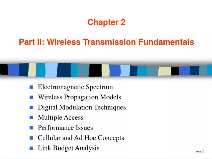
Chapter 2 Part II: Wireless Transmission Fundamentals. Electromagnetic Spectrum Wireless Propagation Models Digital Modulation Techniques Multiple Access Performance Issues Cellular and Ad Hoc Concepts Link Budget Analysis. Electromagnetic Waves.

E N D
Chapter 2Part II: Wireless Transmission Fundamentals Electromagnetic Spectrum Wireless Propagation Models Digital Modulation Techniques Multiple Access Performance Issues Cellular and Ad Hoc Concepts Link Budget Analysis
Electromagnetic Waves • predicted by British physicist James Maxwell in 1865, and observed by German physicist Heinrich Hertz in 1887 • These waves are created by the movement of electrons and have the ability to propagate through space. • using appropriate antennas, transmission and reception of electromagnetic waves through space becomes feasible. • the speed of electron vibration determines the wave’s frequency. • Hertz: how many times the wave is repeated in 1 sec. (to honor Heinrich Hertz)
Wavelength and Amplitude • l = wavelength, f = frequency, c = speed of light
Electromagnetic Spectrum • spectrum: range of electromagnetic radiation • band: spectrum parts
Radio Waves • HF band enables worldwide transmission: • HF signals are reflected off the ionosphere and thus can travel very large distances
Microwaves • small wavelengths compared to radio waves • easily attenuated by objects
Infrared • emitted by very hot objects • such as human body (night vision applications) • frequency depends on the temperature of the emitting body • line-of-sight, point-to-point • of no use outdoors (interfered by heat of sun) • short-rang: 10 meters • IrDA: Infrared Data Association
Microwave and Infrared Bands • Most wireless networking traffic is in the microwave frequency bands. • some licensed, some unlicensed • Infrared: • for short-range wireless communication
Spectrum Regulation • ITU = Int’l Telecommunications Union • a worldwide spectrum regulation org. • the world is split into 3 parts: • American continent • Europe, Africa, and former Soviet union • rest of Asia and Oceania • Rules of assigning spectrum • lottery • auction • comparative bidding • such as pricing, technology, etc.
Licensed Microwave Band • Examples: cellular, paging, PCS • Use of a license is typically in an order of 10 years. • A company can’t have the license and not use it. • Bandwidth is regarded as a resource that the public wants and needs.
Unlicensed Microwave Band • Also on the same microwave band, but no license required. • To avoid interfering primary (licensed) users, spreading spectrum is required. • Two types: • FHSS: Frequency-hopping spread spectrum • DSSS: Direct sequence spread spectrum • Also known as ISM band. • industrial, scientific, and medical
Model of Wireless Propagation Free space path loss Doppler shift Slow/fast fading Error modeling
Shannon’s Formula • an upper bound on the bit rate W of any channel of bandwidth H Hz: W = H log2(1 + S/N) S/N = signal to thermal noise ratio • However, in real world, the upper bound is difficult to achieve due to: • free space path loss • proportional to r-2, where r is the distance between transmitter and receiver (sometimes at higher exponent) • Doppler shift • a signal transmitter and receiver are moving relative to one another • slow/fast fading
Definitions • Reflection: • when an electromagnetic wave falls on an object with dimension very large compared to the wave’s wavelength • Scattering: • when obstructed by objects with dimensions in the order of the wavelength • Diffraction (or shadowing): • when the wave falls on an impenetrable object • in which case, the secondary waves are formed behind the obstructing body
Fast Fading: Multipath Effect • waves traveling along different paths may be completely out of phase when they reach the antenna (thereby canceling each other)
Multipath propagation delay can degrade performance in indoor/outdoor environment. • When the path length differences are short, the effect is smaller. • multipath fading is also referred as fast fading • When LOS (line of sight) exists, this kind of fading is known as Ricean Fading • When LOS does not exist, this kind of fading is known as Rayleigh Fading
We say that the relative strength of signal x, P(x), to that of signal y, P(y), is D dB, if D = 10 log10(P(x)/P(y)) In free space, the average path loss (PL) at a distance of r is (in dB): PL(r) = PL(r0) + 10n log(r/r0) r0 = reference distance (typically 1 Km for macrocells; and 100 m for microcells) n = environmental factor (typically >= 2) To take into account of the shadowing effect PL(r) = PL(r0) + 10n log(r/r0) + Xd Xd = zero-mean Gaussian random variable with standard deviation d Propagation Models
Digital Modulation Techniques Binary Modulation Phase Shift Keying Minimum Shift Keying p/4-Shifted QPSK
Basics • Convert digital stream into the analog signal A(t)cos(wt + ), where w = 2f. • The characteristics in this formulation that may be changed are: • amplitude • frequency • phase • Ex: ASK = amplitude shift keying; FSK = frequency shift keying; PSK = phase shift keying
Most systems modulate the information onto a carrier centered in a (small) allocated spectrum.
Binary Modulation Scheme • Amplitude Shift Keying (ASK): • using ON/OFF to represent 1/0 • “keying”: like a telegraph key • Frequency Shift Keying (FSK): • 1/0 represented by two different frequencies separated by some distance
Binary Phase Shift Keying • Binary Phase Shift Keying (BPSK) • use alternative sine wave phases to encode bits • simple to implement • very robust, used extensively in satellite communications
Quarternary Phase Shift Keying • QPSK: • multi-level modulation: 2 bits per symbol • more spectrally efficient, more complex receiver
Differential PSK (DPSK) • 1 = changing the phase relative to the previous symbol by some amount • 0 = having the same phase as the previous symbol • adv: self-clocked
coding by bit pairs varying the phase of the current bit pair to the phase of the previous bit pair by a multiple of /4 example: 101001 (Fig. 2.27) (i.e., -p/4, -p/4, +5p/4) /4-Shifted QPSK
Hybrid of PSK + ASK • QAM = Quadrate Amplitude Modulation • mixture of PSK and ASK • 3 bits at a time
Multiple Access defining how nodes in a wireless network to share a common medium
Objectives • MAC layer is to define how a user access a channel when he needs one. • Random access: ALOHA and CSMA • Ordered access: Token bus and Token Ring • Deterministic access: FDMA, TDMA, and CDMA • Combinations: TDMA-over-FDMA, TDD-CDMA, and TDMA/CSMA
FDMA • frequency division multiple access ** NMT = nordic Mobile Telephony
TDMA • time division multiple access
CDMA • code division multiple access • each station has a “station code” • each bit is encoded by station code • code 1 is mapped to 1 • code 0 is mapped to -1
ALOHA • A type of packet-radio network. • The first well-known wireless network as well as network system. • Very simple, but not efficient! • Variations: • pure-ALOHA: whenever desired, send the packet • slotted-ALOHA: further divide time axis into slots
CSMA • Before sending, sense the carrier.
Persistent and Non-persistent CSMA • Persistent CSMA: • when the medium is busy, a station can persistently wait for the medium to become idle, and then transmit with a probability p • This is called 1-persistent or p-persistent CSMA. • Non-persistent CSMA: • A station can stop monitoring the wireless medium, and listen to the medium again at predefined time.
Hidden-Node Problem • CSMA has the following problem: • when two nodes are too far away, carrier sensing is difficult
CSMA/CA • CA = collision avoidance • sender first does carrier sense • sender broadcasts RTS (request to send) to receiver • receiver broadcasts CTS (clear to send) to sender • then send data packet • Q: Is CSMA/CD possible in wireless network?
Ordered MAC Techniques • Can a token-ring or token-bus protocol be applied to a wireless network? • Problems: • mobility (nodes joining or leaving the ring) • token loss
Comparison and Summary • Random access: CSMA • under light load: fast response time • under heavy load: throughput declines • simplicity • Deterministic protocols: TDMA, FDMA • guaranteed bandwidth • larger average delay • small delay variance • Hybrid: CSMA/TDMA • adaptive, higher overhead
Spread Spectrum FHSS DSSS
Spread Spectrum Technology • Spread spectrum must be used in ISM band. • Two major technologies: • Frequency Hopping SS (FHSS) • Direct Sequence SS (DSSS) • Located at the PHY of the network stack:
Most Wireless LANs use the ISM bands as secondary users. They must use SS in order not to interfere with the primary users. FHSS: send info in different frequencies on different time slots. Hopping Pattern In each time slot, the occupied frequencies are separated by some distance to avoid interference. FHSS
FHSS is different from FDM (frequency division multiplexing). • Example: (Fig. 4.7) • In the 2.4 GHz band of ISM, we have a space of 80 MHz. (2400~2483MHz) • A typical bandwidth of the information signal is 1 MHz. • Maximum occupancy is 1MHz regulated by FCC. • One time slot = 0.1 sec.
Primary vs. Secondary Users • In FHSS, a typical power limit is 1 watt. • For primary users, the power limit is much larger. • So the interference from FHSS will not be noticeable primary users. • For FHSS secondary user, • when there is 1 primary user there will be a throughput loss of 1/80 = 1.25%; • when there are 2 primary users there will be a throughput loss of 2/80 = 2.5%. • fig 4.8
primary user primary user
DSSS • The input data stream is transferred to a chip stream that is x times higher by XOR. • a chip is 0 or 1, but is called so to distinguish from a bit • example: x = 11, 13, 15, 16 chips/bit
The frequency spectrum is spread out and the spectral energy is x times lower. • It’s so low that primary users are not interfered.
Comparison of Interference • Degradation due to existence of interference: • FHSS: linear to the level of interference • DSSS: • degraded by half after a certain point (since it typically occupies 50% of the bandwidth) • won’t work after a certain level