Download
1 / 13
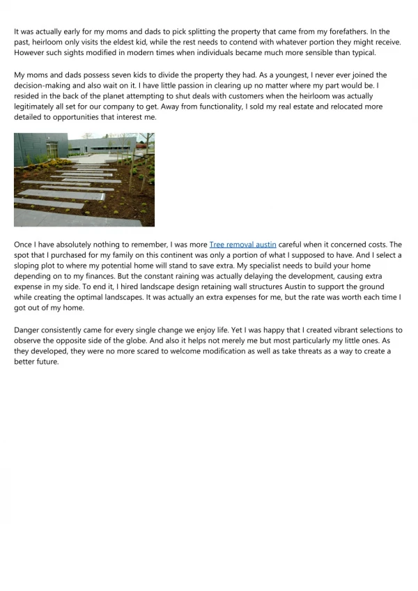
831 likes | 4.09k Views
Design of Cantilevered Retaining Walls. CE A433 – RC Design T. Bart Quimby, P.E., Ph.D. Spring 2009. Introduction. A cantilever retaining wall is a system of cantilever slabs (i.e. beams) that retain soil. The key is to draw the appropriate FBDs so that you can determine the internal forces.

E N D
Design of Cantilevered Retaining Walls CE A433 – RC Design T. Bart Quimby, P.E., Ph.D. Spring 2009
Introduction • A cantilever retaining wall is a system of cantilever slabs (i.e. beams) that retain soil. • The key is to draw the appropriate FBDs so that you can determine the internal forces.
Cantilever Retaining Wall Stem Toe Heel Shear Key
Forces ACTING ON the Wall Soil on Heel Active Lateral Soil Pressure Wall Soil on Toe Footing Shear Key
Reactions ACTUAL FRICTION is not the same as FRICTION CAPACITY! Passive Lateral Soil Pressure Friction Vertical Reaction
Computing Soil Bearing Stress • Resolve applied forces into a concentric vertical force and moment on the contact area. • Ix = bL3/12 • A = bL • c = L/2 • smax = P/A + Mc/Ix • smin = P/A – Mc/Ix P M
Sliding Vslide =Driving Force = Demand Vresist = sum(Resisting Forces) = Capacity Driving Force Resisting Capacity FS = Vresist / Vslide Design for FS > 1.5 Friction CAPACITY = m N Not Actual Friction Reaction
Overturning MOT =Driving Force*arm = Demand Resisting Forces MROT = sum(Resisting Moments) = Capacity Driving Force FS = MROT / MOT Design for FS > 2.0 Point of Rotation
Draw FBDs Stem Toe Heel
Stem Diagrams Moment Shear FBD Make stem thick enough for shear Capacity Add T&S Steel Demand Capacity Demand Select Steel to provide flexural capacity
Toe Add T&S Steel Vu can be calculated a distance ‘d’ from face of wall since there is a compressive reaction with the wall. Flexural Steel extends a development length into the heel and should develop within the length of the toe. Design Shear Shear Mu is computed at the face of the wall. Design Moment Moment
Heel Vu must be calculated at the face of wall since there is a tensile reaction with the wall. Flexural Steel extends a development length into the toe and should develop within the length of the heel. Add T&S Steel Design Shear Shear Mu is computed at the face of the wall. Design Moment Moment
The Design Process • Select the overall dimensions (height, embedment, footing length and position, and estimated footing & wall thicknesses) based on stability (sliding and overturning) and soil strength (max/min bearing pressures) using service level loads. • Check slab (wall and footing) thicknesses using shear criteria and factored loads. Adjust thicknesses as necessary, rechecking stability and soil strength of the values change. • Select the flexural steel for the three cantilever slab elements using factored loads. • Select the temperature and shrinkage steel for wall and footing. • Draw the resulting wall cross section (to scale!)