Download
1 / 19
190 likes | 409 Views
AT40K Training. AT40K/40KAL Configuration Modes. Atmel Corporation 2325 Orchard Parkway San Jose, CA 95131 Hotline (408) 436-4119 fpga@atmel.com OR configurator@atmel.com. AT40K/40KAL Configuration Modes. Compatible Modes Mode 0 Master Serial (Mode 4 on AT6K)

E N D
AT40K Training AT40K/40KAL Configuration Modes Atmel Corporation 2325 Orchard Parkway San Jose, CA 95131 Hotline (408) 436-4119 fpga@atmel.com OR configurator@atmel.com
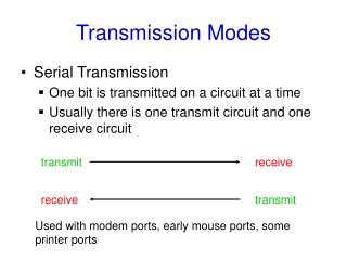
AT40K/40KAL Configuration Modes • Compatible Modes • Mode 0 Master Serial (Mode 4 on AT6K) • Mode 7 Slave Serial (Mode 3 on AT6K) • Atmel-Specific Modes • Mode 1 Slave Serial (Mode 3 on AT6K) • Mode 2 Slave Parallel (Mode 6 on AT6K) • Mode 6 Slave Parallel with Address Count Up (Mode 1 on AT6K) • Mode 4 Slave Synchronous RAM Mode (New Co-processor Interface) NOTE: AT6K modes are provided as points of reference only. Implementation details for the AT6K architecture do differ.
Optional Active AT40K/40KAL Configuration I/O • Dedicated Pins (all modes) • M2, M1, M0, RESET, CON, CCLK • Dual Use Pins • INIT (all modes) • CSOUT, CHECK, CS1, CS0, A(23:0), D(15:0), HDC, LDC
Mode 0 • 1, 2, 4 or 8 MHz internally-generated CCLK set through Bitstream options • Configurator RESET pin may be tied to either FPGA RESET or INIT pin
Mode 1 or Mode 7 • External clocking up to 40 MHz • Microprocessor- or EEPROM-driven • Mode 7 does not require use of CS0 • M2 M1 M0 • Mode 1 0 0 1 • Mode 7 1 1 1
Mode 1 Parallel • Allows independent programming of multiple FPGAs in parallel with the same data • M2 M1 M0 • Mode 1 0 0 1
Mode 1 Cascade • Uses CS0 to propagate chip select between cascaded FPGAs; Xilinx devices propagate data • M2 M1 M0 • Mode10 0 1
Mode 2 • External clocking up to 40 MHz • Sub-millisecond configuration • Microprocessor- or EEPROM-driven
Mode 2 Parallel • Allows independent programming of FPGAs
Mode 2 Cascade • Uses CS1 to propagate chip select between cascaded FPGAs; Xilinx devices propagate data
Mode 6 • External clocking up to 40MHz • Sub-millisecond configuration
BYTE n BYTE n BYTE... BYTE... BYTE 2 BYTE 2 BYTE 1 BYTE 1 BYTE 0 BYTE 0 AT40K/40KAL Logical Memory Map BYTE n BYTE n Z BYTE... BYTE... Z Core Cells BYTE 2 BYTE 2 BYTE 1 BYTE 1 Cell Y Location Vertical Repeaters BYTE 0 BYTE 0 Horizontal Repeaters North/South I/O Cell 0,1 Cell 1,1 And so on ........ Z Z TAG Addressed PAGES 4 Dimensional Memory Map • Tag Defines Page being written. • X,Y Define Array Location. • Z defines which byte at a given X,Y Location is written. Cell 0,0 Cell 1,0 Cell X Location
Example Bitstream Serial data is read in MSB first. Byte/word entries above are shown MSB<->LSB. Not applicable to Mode 4.
Mode 4 • Mode designed for CacheLogic applications • Device treated as an SRAM by the system • Microprocessor treats FPGA as memory mapped I/O. • Simple 24 bit Address and 8 or 16 bit Data structure. LSB MSB X Address Tag Data Z Address Y Address 8 Bits 8 Bits 8 or 16 Bits 4 Bits 4 Bits 32 or 40 Bit word defines address and data Information for one byte per clock cycle 0 31 or 39
AT40K/40KAL Memory Map and CacheLogic • Memory map is architected to support CacheLogic Applications. • Memory Map Pages are all dissociated. • Writing data to one structure has NO impact on any other structure. Key requirement for CacheLogic. • Simple 32 or 40 bit interface and 33MHz clocking allow very rapid caching of logic functions. • Symmetrical FPGA architecture results in simple and predictable CacheLogic designs. • Each memory byte has a unique memory map location and can be individually addressed. • Data can be loaded x8 or x16 for faster reconfiguration. • In full bitstream, X, Y, Z, Tag information is handled by the on-chip control logic.
AT40M Development Board • Design verification of AT40K/40KAL FPGAs • Built-in support for Configuration processes • Mode 0 • Program Configurator • Boot from Configurator • Mode 7 • Download direct to FPGA • Mode 1 • Download direct to FPGA with CS0
FPGA Starter KitATSTK40 • Get Going with FPGAs text book • Complete IDS6.0 FPGA software • Comprehensive development board • 10 Design examples • AT40K20 SRAM FPGA w/FreeRAM • AVRMega Microcontroller • AT17C512 Configurator • 1 DAC • 2 ADCs • 2 Serial Ports • Infrared sensor • Programmable switches & LEDs • LCD Drivers • Cables & Interfaces ATSTK40 FPGA Starter Kit $149 Complete