Download
1 / 1
10 likes | 130 Views
Dynamic Refraction Stereo. 1. Dynamic Refraction Stereo Problem. Goal: Reconstruct instantaneous height map & normal map of time-varying refractive surface projecting to 2 cameras Calibrated & synchronized cameras

E N D
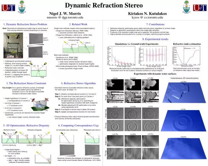
Dynamic Refraction Stereo 1. Dynamic Refraction Stereo Problem • Goal: Reconstruct instantaneous height map & normal map of time-varying refractive surface projecting to 2 cameras • Calibrated & synchronized cameras • Arbitrary, time-varying surface shape (i.e. no prior shape models) • Refractive index unknown • Calibrated pattern at known 3D position, visible through liquid • Known 1-1 mapping from pixels q to points C(q) on pattern Cam1 (time t) Cam2(time t) n p 3. The Refraction Stereo Constraint • Key insight: For a generic refractive surface, knowledge of pixel q & pattern point C(q) defines a constraint curve in the 3D space of possible normals & refractive index values • Height hypothesis in Camera 1correspondence in Camera 2 • q & C(q) in Camera 1 1st constraint curve • q’ & C(q’) in Camera 2 2nd constraint curve • Generically, curves do not intersect for incorrect height hypotheses can resolve height, normal, refractive index 5. 1D Optimization: Refractive Disparity 6. Computing Correspondence C(q) Refracted view (time t) Bonfort & Sturm Refractive Disparity Un-refracted view (reference) n1 n2 n1 n2 n2 n1 p d1 d2 minimize ||d1||2 + ||d2||2 minimize angle(n1,n2) • Large liquid heights: both criteria are 0 when p on ‘true’ surface • As height → 0 estimation of n1, n2 unstable ||d1||2 + ||d2||2 remains stable (reduces to standard stereo) n1 n2 Iteratively compute flow between un-refracted & refractedviews using Lucas-Kanade (Baker & Matthews, IJCV 2004) Nigel J. W. Morrisnmorris @ dgp.toronto.edu Kiriakos N. Kutulakoskyros @ cs.toronto.edu 7. Contributions 2. Related Work • Refractive disparity optimization gives stable reconstructions regardless of surface shape • Require no geometric assumptions other than single light refraction • Produces a full resolution height map and a separate, full-resolution normal map • Highly-detailed reconstructions for a variety of complex, deforming liquid surfaces • Single-view methods (require extra assumptions/optics): • Shape from Distortion (Murase, PAMI 1992) assumes constant mean distance • Shape from Refraction (Jähne et al., JOSA 1994)uses collimating lens & lighting gradient • Multi-view methods: • Sanderson et al. (PAMI 1998), Bonfort & Sturm (ICCV 2003)static mirror scenes (known refractive index), optimization degrades for shallow liquid heights • Multi-media photogrammetry (Flach & Maas, IAPRS 2000) known parametric shape model 8. Experimental results Simulations vs. Ground-truth Experiments Refractive index estimation q Total reconstruction error as function of refractive index (liquid was water) Observed results (solid red) vs simulated results (dotted blue)for 0.08 pixel localization error for set of planar refractive surfaces at various heights Experiments with dynamic water surfaces C(q) t=1.32s Instantaneous 3D reconstructions t=0.6s t=0.92s t=0.92s 4. Refractive Stereo Algorithm Height map • Discretize interval of possible refractive index values.For each value, do Steps 1-4: • Step 1: Initialize correspondence function C(.) for time 0 • Step 2: For each time t and each pixel q in Camera 1 • 2a:(Refractive disparity optimization) 1D optimization along ray of q, searching for height hypothesis consistent with both viewpoints • 2b: (Bundle adjustment) 5D optimization of p and n using reprojection error • Step 3: Fuse depth & normal map to obtain 3D surface • Step 4: Update correspondence function for next frame • Choose refractive index value minimizing total reconstruction error (across all frames and pixels) Tilt map q’ q n p t=0.4s t=0.3s t=0.35s t=0.3s C(q’) C(q) Height map Tilt map t=0.91s t=0.75s t=0.83s t=0.91s Height map Tilt map