Download
1 / 1
20 likes | 159 Views
Triplet Quad. Sextupole. Skew Quad. Hor. Dip. Ver. Dip. D1. coil aperture. [mm]. 120. 140. 140. 140. 140. 180. field. 120/102 a T m -1. -/- b. -/-. -/0.33 T. 0.33 T /-. 4.04 T. mechanical/magnetic length. [m]. 10.784/ 10.324. 0.40/ 0.25. 0.80/ 0.50. 1.81/ 1.42.

E N D
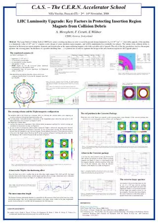
Triplet Quad. Sextupole Skew Quad. Hor. Dip. Ver. Dip. D1 coil aperture [mm] 120 140 140 140 140 180 field 120/102a T m-1 -/-b -/- -/0.33 T 0.33 T /- 4.04 T mechanical/magnetic length [m] 10.784/10.324 0.40/0.25 0.80/0.50 1.81/1.42 1.81/1.42 4.50/3.7 Cold Bore Tube thickness [mm] 3.17 3.17 3.17 3.17 3.17 5.6 Beam Screen thickness [mm] 2c 2 2 2 2 1.7d longitudinal distance from previous element [m] 22.735e 1.26 0.10 0.20 0.20 1.335 longitudinal inter-module distance [m] 1.235 - - - - 0.5 Figure 5 – Corrector Package transverse sections: skew quadtrupole (left) and horizontal dipole (right). C.A.S. – The C.E.R.N. Accelerator School Villa Vecchia, Frascati (IT) – 2nd - 14th November, 2008 LHC Luminosity Upgrade: Key Factors in Protecting Insertion Region Magnets from Collision Debris A. Mereghetti, F. Cerutti, E.Wildner CERN, Geneva, Switzerland Abstract.The Large Hadron Collider built at CERN now enters a starting-up phase in order to reach the present design luminosity (L0) of 1034 cm-2 s-1. A possible upgrade of the machine to a luminosity value of 1035 cm-2 s-1 requires a new design of some insertion region magnets, and will be implemented in essentially two phases. The energy from collision debris is deposited in the insertion region magnetic elements and in particular in the superconducting magnet coils with a possible risk of quench. The role of the key parameters (such as the magnet aperture, the crossing plane, the thickness of a possible shielding liner, …) is pointed out, in order to optimize the design of the new insertion regions for the Upgrade phase I. • The considered scenario [1] • (see Table 1 and Figures 1-5) • luminosity: 2.5 1034cm-2 s-1; • 225µradhalf crossing angle; • no experimental vacuum chamber; • TAS aperture: 45 mm; • FDDF Triplet [2] wrt the horizontal plane (analytical implementation of the magnetic field); • recommended limit for power deposition (in Rutherford cable): 4.3 mW cm-3; • The deposited power density from the collision debris was computed with FLUKA [3-4] for the I.R. elements (from TAS up to the D2). Values are given as volume fractions. Table 1 – Geometrical and magnetic parameters of the simulations. a (Q1-Q3)/(Q2a-Q2b) b IP1/IP5 c Beam Screen extra shielding thickness in Q1: 10.15 mm d Actually, a Worm Bore Tube e From IP Figure 4 – Triplet quadrupole transverse section – geometric detail and materials. The thick B.S. in figure is envisaged only for the first magnet (Q1, see Table 1 note c). • Figure 1 (on the left) - Schematic layout of the LHC. The ATLAS experiment corresponds to the Interaction Point 1 (with vertical crossing scheme), whereas the CMS experiment corresponds to the Interaction Point 5 (with horizontal crossing scheme). • Figure 2 (below): the actual IP1 layout as presently installed in the LHC tunnel. • Figure 3 (on the right): the FLUKA implementation of the LHC Insertion Region Upgrade Phase I. • The crossing scheme and the Triplet magnetic configuration • The magnetic field of the Triplet has a dramatic effect in collecting the collision debris cone, implying an accurate evaluation of the power deposition in the coils. • The crossing plane (vertical/horizontal) corresponds to the longitudinal plane where the peak power in the superconducting coils is located (see Figures 6 and 8). • The Triplet has a double effect: • it inverts the transverse component of the collision debris momentum (up/down for vertical crossing and outer/inner for horizontal crossing) (see Figure 6); • in case of vertical crossing the collision debris exiting the Triplet is defocused, impacting more seriously the elements immediately downstream. Conversely, in case of horizontal crossing, the collision debris is focused, thus less harmful for the Corrector Package. See the different derivatives of the peak power profile at the exit of the Triplet (about 70m from the IP) in the top frame of Figure 6 and the peak power values at the beginning of the Corrector Package in the top frame of Figure 8. The coil position in the Corrector Package While the coils in the Triplet are centered on the crossing planes, some elements of the corrector package take advantage of a more favorable position of their coils (see Figure 8). Figure 8 – (left) Longitudinal distributions of the peak power density in the Corrector Package super-conducting cables and the total power on the Corrector Package elements for vertical and horizontal crossing. (Right) 2D-map of the power density in the skew quadrupole and in the horizontal and vertical dipole correctors at the longitudinal peak for both the crossing schemes. A liner in the Corrector package A Cu liner has been inserted in the gap between the CBT and the coil aperture of all the corrector package elements (see Figure 5): there is a clear benefit on all the magnetic elements with the exception of the front face of the first element, since there the effective thickness of the shield is too small (see Figure 9). Figure 6 – (left) Longitudinal distributions of the peak power density in the Triplet inner cable and the total power on Triplet elements for vertical and horizontal crossing. (Right) 2D-map of the power density in Q2a and Q3 at the longitudinal peaks for both crossing schemes. A liner in the Triplet: the shadowing effect Since the beam size in Q1 is smaller than in the other three triplet magnets (Q2a, Q2b and Q3), the larger clearance between the beam envelope and the magnet aperture allows to lodge a thick liner in Q1, efficiently shielding the front face of Q2a (see Figure 7), in addition to the Q1 itself. Figure 9 – Longitudinal distributions of the peak power density in the Corrector Package super-conducting cables and the total power on the Corrector package elements for vertical crossing, with and without the Cu liner. The corrector larger aperture An estimate of the power deposition in coils in case of a 120 mm corrector package aperture (same as the Triplet one) shows the significant benefit of an increased aperture wrt the Triplet one (namely a factor of 2 on the sextupole). Note how the vertical dipole, the coils of which are on the debris plane, is pushed towards the recommended limit. Figure 7 (Right) – Peak power density in the Triplet inner cable for different shielding thicknesses. The study refers to a 130 mm aperture for vertical crossing. The interconnection length The distance between subsequent elements is responsible for the increase of the load on the front face of the downstream magnet. This can be appreciated looking at the jumps clearly visible in the peak longitudinal profile, between the end of a module and the beginning of the following one. Figure 10 – Longitudinal distribution of the peak power density in the Corrector Package super-conducting cables for vertical crossing for 140 mm aperture, with and without the Cu liner, and for 120 mm aperture. REFERENCES [1] http://www.cern.ch/liuwg [2] R. Ostojic, LHC Project Report1094 (2008). [3] A. Fasso`, A. Ferrari, J. Ranft, P.R. Sala, CERN Yellow Report 2005-10 (2005). [4] G. Battistoni et al., “The FLUKA code: Description and Benchmarking“, Proceedings of the Hadronic Shower Simulation Workshop 2006, Fermilab 6-8 September 2006, M. Albrow, R. Raja eds., AIP Conference Proceedings, 31-49 (2007). ACKNOWLEDGEMENTS The authors wish to thank A. Ferrari, P. Fessia, M. Karppinen, M. Mauri, J. Miles, R. Ostojic, E. Todesco for essential and valuable input information and very useful discussions.