Download
1 / 64
640 likes | 783 Views
High-Capacity Packet Switches. Switches with Input Buffers (Cisco). Packet Switches with Input Buffers. Switching fabric Electronic chips (Mindspeed, AMCC, Vitesse) Space-wavelength selector (NEC, Alcatel) Fast tunable lasers (Lucent) Waveguide arrays (Chiaro) Scheduler

E N D
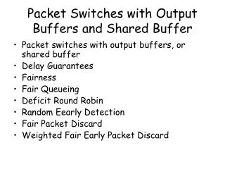
Packet Switches with Input Buffers • Switching fabric • Electronic chips (Mindspeed, AMCC, Vitesse) • Space-wavelength selector (NEC, Alcatel) • Fast tunable lasers (Lucent) • Waveguide arrays (Chiaro) • Scheduler • Packets compete not only with the packets destined for the same output but also with the packets sourced by the same input. Scheduling might become a bottleneck in a switch with hundreds of ports and gigabit line bit-rates.
Optical Packet Cross-bar (NEC,Alcatel) • A 2.56 Tb/s multiwavelength and scalable switch-fabric for fast packet-switching network, PTL 1998,1999, NEC
Optical Packet Cross-bar (Lucent) • A fast 100 channel wavelength tunable transmitter for optical packet switching, PTL 2001, Bell Labs
Scheduling Algorithms for Packet Switches with Input Buffers • In parallel iterative matching (PIM), SLIP or dual round-robin (DRR) inputs send requests to outputs, outputs grant inputs, and inputs then grant outputs in one iteration. It was proven that PIM finds a maximal matching after log2N +4/3 steps on average. • Maximum weighted matching and maximum matching algorithm maximize the weight of the connected pairs, and achieve 100% for i.i.d. traffic but have complexities O(N3log2N) and O(N2.5). • Sequential greedy scheduling is a maximal matching algorithm that is simple to implement. Maximal matching algorithm does not leave input-output pair unmatched.
PIM, SLIP and DRR • In PIM and SLIP each input sends requests to all outputs for which it has packets, and in DRR only to one chosen output. SLIP and DRR use round-robin choices. • Theorem: PIM finds a maximal matching after log2N +4/3 steps on average. • Proof: Let n inputs request output Q, and let k of these inputs receive no grants. With probability k/n all requests are resolved, and with probability 1-k/n at most k requests are unresolved. The average number of requests is at most (1-k/n)·k≤n/4. So if there are N2 requests at the beginning, the expected number of unresolved requests after I iterations is N2/4i
PIM, SLIP and DRR • Proof (cont.): Let C be the last step on which the last request is resolved. Then:
SGS Implementation • All inputs one after another choose outputs, SGS is a maximal matching algorithm
SGS Uses Pipelining Ii -> Tk Input i chooses output for time slot k
Bandwidth ReservationsPacket Switches with Input Buffers • Anderson et al.: Time is divided into frames of F time slots. Schedule is calculated in each frame; Statistical matching algorithm. • Stiliadis and Varma: Counters are loaded per frame. Queues with positive counters are served with priority according to parallel iterative matching (PIM), their counters are then decremented by 1. DRR proposed by Chao et al. could be used as well. • Kam et al.: Counter is incremented for the negotiated bandwidth and decremented by 1 when the queue is served. Maximal weighted matching algorithm is applied. • Smiljanić: Counters are loaded per frame. Queues with positive counters are served with priority according to the maximal matching algorithm preferrably sequential greedy scheduling algorithm (SGS), where inputs sequentially choose outputs to transmit packets to.
Weighted Sequential Greedy Scheduling • i=1; • Input i chooses output j from Ok for which it has packet to send; Remove i from Ik and j from Ok; • If i<N choose i=i+1 and go to the previous step;
Weighted Sequential Greedy Scheduling • If k=1 mod F then cij=aij; Ik={1,...,N}; Ok={1,...,N}; i=1; • Input i chooses output j from Ok for which it has packet to send such that cij>0; Remove i from Ik and j from Ok; cij=cij-1; • If i<N choose i=i+1 and go to the previous step;
Performance of WSGS Theorem: The WSGS protocol ensures aij time slots per frame to input-output pair (i,j), if where Ti is the number of slots reserved for input i, and Rj is the number of slots reserved for output j. Proof: Note that
Analogy with Circuit Switches • Inputs ~ Switches in the first stage • Time slots in a frame ~ Switches in the middle stage • Outputs ~ Switches in the last stage Non-blocking condition: Strictly non-blocking condition:
I: II: III: Admission Control for WSGS The WSGS protocol ensures aij time slots per frame to input-output pair (i,j) if: F frame length Ti the number of slots reserved for input i, Rj the number of slots reserved for output j. ti, rjare normalized Ti, Rj.
Non-blocking Nature of WSGS • Maximal matching algorithm does not leave input or output unmatched if there is a packet to be transmitted from the input to the output in question. • It can be proven that all the traffic passes through the cross-bar with the speedup of two which is run by a maximal matching algorithm, as long as the outputs are not overloaded.
Rate and Delay Guranteed by WSGS • Assume a coarse synchronization on a frame by frame basis, where a frame is the policing interval comprising F cell time slots of duration Tc. • Then, the delay of D=2·F·Tc is provided for the utilization of 50%. Or, this delay and utilization of 100% are provided for the fabric with the speedup of 2.
bit-rate reserved for multicast session k of input i multicast group k sourced by input i Port Congestion Due to Multicasting Solution: Packets should be forwarded through the switch by multicast destination ports.
Admission Control for Modified WSGS where Ei is the number of forwarded packets per frame
Admission Control for Modified WSGS Modified WSGS protocol ensures negotiated bandwidths to input-output pairs if for : I: II: F frame length, P forwarding fan-out Ti the number of slots reserved for input i, Ri the number of slots reserved for output i. ti, riare normalized Ti, Ri.
Rate and Delay Guaranteed by Modified WSGS • Assume again a coarse synchronization on a frame by frame basis. • Then, the delay of D= F·Tc is provided for the utilization of 1/(P+2), where P is the forwarding fan-out. Or, this delay and utilization of 100% are provided for the fabric speedup of P+2.
Load Balancing in Packet Switches • J. Turner introduces load balancing of multicast sessions in Benes packet switches, INFOCOM 1993 • C. Chang et al. propose load balancing in two-stage Birkhoff-von-Neumann switch, while Iyer et al. analyze the performance of the parallel plane switch (PPS) which applies load balancing. • Keslassy et al. propose the implementation of high-capacity PPS or Birkhoff-von-Neumann architecture. • Smiljanić examines rate and delay guarantees in three-stage Clos packet switches based on load balancing. These switches provide the larger number of lower speed ports.
Load Balancing Algorithms • Packets are split into cells, and cells are grouped into flows. • Cells of each flow are balanced over center SEs • Balancing of a flow can be implemented in the following way: • One counter is associated with each flow. • When a cell of the flow arrives, it is marked to be transmitted through the center SE whose designation equals the counter value, and then counter is incremented (decremented) modulo l, where l is the number of center SEs.
Load Balancing Algorithms • A flow comprises cells determined by different rules, but that have the same input port or the input switching element (SE), and have the same output port or the output SE. Examples: • SEs with input buffers • Cells sourced by the same input • Cells sourced by the same input bound for the same output • Cells sourced by the same input bound for the same output SE • SEs with shared buffers • Cells sourced by the same input SE bound for the same output • Cells sourced by the same input SE bound for the same output SE
Non-Blocking Load Balancing l Non-blocking if: , no speedup is needed
= D 4 FT c Rate and Delay Guarantees • Let us assume the implementation with the coarse synchronization of the switching elements (SEs), i.e: • the switching elements are synchronized on a frame-by-frame basis • in each frame any SE passes cells that arrived to this SE in the previous frame • The delay through a three-stage Clos network with such coarse synchronization including packet reordering delay is: • Note that if multicasting is accomplished by the described packet forwarding, the utilization is decreased 3 times, and the delay is increased logPN times.
Utilization Formula • Utilization under which the delay is guaranteed to be below D: • where S is the switching fabric speedup, Nf is the number of flows whose cells pass the internal fabric link, and Tc is the cell time slot duration.
Derivation of Utilization • The maximum number of cells transmitted over a given link from an input to a center SE, Fc, fulfills: • where fig is the number of cells per frame in flow g of cells from input SE i, and Fu is the maximum number of cells assigned to some port • If Nf -n flows have one cell per frame, and remaining n flows are assigned max(0,nFu-Nf+n) cells per frame
Derivation of Utilization • So: • The same expression holds for Fc and Ua over the links from center to output SEs • Since F=D/(4Tc):
Speedup Formula • The delay of D is guaranteed for 100% utilization for the speedup of: • where Nf is the maximum number of flows whose cells pass any internal fabric link, and Tc is the cell time slot duration.
Derivation of Speedup • We put Ua=1 in the formula for utilization, and readily obtain expression for the required speedup:
Counter Synchronization • The utilization was decreased because all flows may be balanced starting for the same center SE, so this SE will not be able to deliver all the passing cells within a frame. • Higher utilization can be achieved if the counters of different flows are synchronized. • Counter of flow g sourced by input SE1i is reset at the beginning of each frame to cig =( i+g ) mod l,where l is the number of center SEs. And, counter of flow g bound for output SE3j is reset at the beginning of each frame to cjg =( j+g ) mod l.
Utilization Formula when Counters are Synchronized • Utilization under which the delay is guaranteed to be below D: • where S is the switching fabric speedup, Nf is the maximum number of flows whose cells pass any internal fabric link, and Tc is the cell time slot duration.
Derivation of Utilization when Counters are Synchronized • The maximum number of cells transmitted over a given link from an input to a center SE2(l-1), Fc, fulfills: • where fig denotes the number of cells in flow g that are balanced starting from input SE1i