Download
1 / 41
410 likes | 547 Views
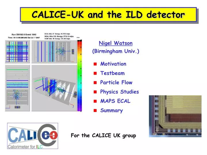
CALICE-UK and the ILD detector. Motivation Testbeam Particle Flow Physics Studies MAPS ECAL Summary. Nigel Watson (Birmingham Univ.). For the CALICE UK group. LEP/SLD: optimal jet reconstruction by energy flow Explicit association of tracks/clusters

E N D
CALICE-UK and the ILD detector • Motivation • Testbeam • Particle Flow • Physics Studies • MAPS ECAL • Summary Nigel Watson (Birmingham Univ.) For the CALICE UK group
LEP/SLD: optimal jet reconstruction by energy flow • Explicit association of tracks/clusters • Replace poor calorimeter measurements with tracker measurements – no “double counting” E/E = 60%/E E/E = 30%/E Mass (jet3+jet4) Mass (jet3+jet4) Little benefit from beam energy constraint, cf. LEP Equivalent best LEP detector Goal at ILC Mass (jet1+jet2) Mass (jet1+jet2) ILC: high performance calorimetry • Essential to reconstruct jet-jet invariant masses in hadronic final states, e.g. separation of W+W,Z0Z0, tth, Zhh, H Nigel Watson / Birmingham
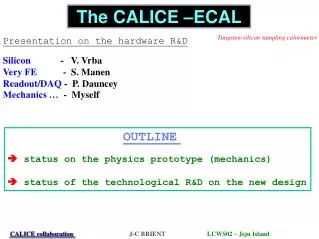
ECAL design principles • Shower containment in ECAL, X0 large • Small Rmoliere and X0 – compact and narrow showers • int/X0 large, EM showers early, hadronic showers late • ECAL, HCAL inside coil • Lateral separation of neutral/charged particles/’particle flow’ • Strong B field to suppresses large beam-related background in detector • Compact ECAL (cost of coil) • Tungsten passive absorber • Siliconpixel readout, minimal interlayer gaps, stability – but expensive… • Develop “swap-in” alternatives to baseline Si diode designs in ILD (+SiD) • e.g. MAPS Nigel Watson / Birmingham
CALICE: from MC to reality to MC CAlorimeter for the LInear Collider Experiment “Imaging Calorimeter” Ultimate goal High granularity calorimeter optimised for the Particle Flow measurement of multi-jet final state at the International Linear Collider Scint. Strips-Fe TCMT • Initial task • Build prototype calorimeters to • Establish viable technologies • Collect hadronic shower data with unprecedented granularity • tune reconstruction algorithms • validate existing MC models Next task Exploit validated models for whole detector optimisation Nigel Watson / Birmingham
Test beam prototypes 10 GeV pion shower @ CERN test beam beam Scint-Fe tail catcher/ muon tracker SiW ECAL Scint-Fe HCAL 1x1cm2 lateral segmentation ~1 X0 longitudinal segment. ~1l total material, ~24 X0 3x3cm2 tiles lateral segmentation ~4.5 l in 38 layers 5x100cm2 strips ~5 l in 16 layer Nigel Watson / Birmingham
The 2006 CERN installation Tail Catcher HCAL ECAL beam AHCAL layer with high granular core readout Nigel Watson / Birmingham
Reality: ECAL linearity/resolution CERN Emeas / GeV Emeas / Ebeam 2006 data (LCWS’07 vintage) Non-linearities ~1% A priori and optimised weightings e- beam energy/GeV DE/E (%) * G4.8.1.p01 DESY Emeas / Ebeam ∆E/E =17.13/√(E/GeV)⊕0.54% 1/sqrt(Ebeam) Nigel Watson / Birmingham
CALICE testbeam outlook to date • Integrated approach to develop optimal calorimety, not just HCAL • Complete understanding of 2006-7 data • Adding yet more realism to testbeam model (material, instrumented regions, etc.) • Understanding beamline – characterisation of beam itself empirically, or by modelling ~accelerator-style the transport line (BDSIM et al?) • Include experience with modelling test beam prototypes into uncertainties in “whole detector” concept models • Detailed study of hadronic shower substructure • Separation of neutrons, e.m., hadronic components, mip-like, …. – “deep analysis” • Data will reduce interaction modelling uncertainties • Useful for particle flow algorithms, in development for detector optimisation, e.g. PandoraPFA Recent developments with PandoraPFA… Nigel Watson / Birmingham
Recent Improvements Overview: • Technical Improvements • minor bug fixes • reduced memory footprint (~ factor 2) by on-the-fly deleting of temporary clusters, rather than waiting to event end • Use of tracks (still TrackCheater) • Photon Identification • EM cluster profile identification • Particle ID • Much improved particle ID : electrons, conversions, KSp+p-, Lp-p (no impact on PFA) • Some tagging of K± m±n and p± m±nkinks • No explicit muon ID yet • Fragment Removal • “Calibration” – some interesting issues… Mark Thomson
e.g. Tracking I : extrapolation ptrack pclust • If a track isn’t matched to a cluster – previously track was dropped (otherwise double count particle energy) • Not ideal – track better measured + direction • Now try multiple (successively looser) track-cluster matching requirements e.g. “circle matching” • As a result, fewer unmatched looping endcap tracks Mark Thomson
Fragment Removal 3 GeV 7 GeV cluster 6 GeV 6 GeV cluster 9 GeV 6 GeV 9 GeV track 9 GeV 9 GeV • One of the final stages of PandoraPFA is to identify “neutral fragments” from charged particle clusters • Previously the code to do this was “a bit of a mess” • This has been significantly improved – but not yet optimised Mark Thomson
Fragment removal : basic idea 6 GeV 4 GeV 9 GeV 3 GeV 9 GeV 5 GeV • Look for “evidence” that a cluster is associated with another 3 GeV 7 GeV cluster 6 GeV cluster 6 GeV 9 GeV track 9 GeV Distance of closest approach Distance to track extrap. Fraction of energy in cone Layers in close contact • Convert to a numerical evidence score E • Compare to another score “required evidence” for matching, R, based on change in E/p chi-squared, location in ECAL/HCAL etc. • If E> R then clusters are merged • Rather ad hoc but works well (slight improvement wrt. previous) Mark Thomson
“Calibration” cont. • Effect depends on cluster energy and isolation cut Isolation cut: 10cm 25cm 50cm Fraction of energy rejected as isolated D = 10 % D = 5 % D = 2.5 % • Non linearity degrades PFA performance • For now increase isolation cut to 25 cm (small improvement for PFA) • Best approach ? Mark Thomson
Current Performance cont. Caveat :work in progress, things will change PandoraPFA v01-01 PandoraPFA v02-a • For 45 GeV jets, performance now equivalent to 23 % / √E • For TESLA TDR detector “sweet spot” at just the right place 100-200 GeV jets ! • However, only modest improvements at higher energy… Mark Thomson
Evolution PandoraPFA v00-a 09/2006 Mark Thomson
Evolution PandoraPFA v01-01 06/2007 Mark Thomson
Evolution PandoraPFA v02-a 09/2007 Mark Thomson
Summary Summary: • Concentrated on lower energy performance – major improvements ! • Also improvements in structure of code + almost certainly some new • Some small improvements for higher energy jets Perspective: • Development of high performance PFA is highly non-trivial • User feedback very helpful (thanks Wenbiao) • Major improvements on current performance possible • “just” needs effort + fresh ideas • PandoraPFA needs a spring-clean (a lot of now redundant code) + plenty of scope for speed improvements • again needs new effort (I just don’t have time) Mark Thomson
What Next Plans: • Optimisation of new code • Slow procedure… takes about 6 CPU-days per variation • Only small improvements expected – have found that the performance is relatively insensitive to fine details of alg. • More study of non-linear response due to isolation • Will look at RPC HCAL • Detailed study of importance of different aspects of PFA, e.g. what happens if kink finding is switched off… • Revisit high energy performance • Update code to use LDCTracking • Release version 02-00 on timescale of 1-2 months. Mark Thomson
Compare PFAs using W+W- scattering All 2-jet mass pairs GeV 2-jet mass pairs, pairing selection GeV [W.Yan, DR Ward] Nigel Watson / Birmingham
Calibration of PFAs is essential to understand ultimate detector capabilities. Mandatory to have “fair”, objective comparisons! Nigel Watson / Birmingham
Higgs self coupling study • Michele slides I • ExploitsPandoraPFA, compares with other public algorithms (Wolf, newertrackbased PFA) • Significantly better performance in Pandora PFA in mean and resolution Z→mm [M.Faucci Giannelli] Nigel Watson / Birmingham
MAPS • Siliconpixel readout, minimal interlayer gaps, stability – prohibitive cost? • UK developing “swap-in” alternative to baseline Si diode designs in ILD (+SiD) • CMOS process, more mainstream: • Industry standard, multiple vendors (schedule, cost) • (At least) as performant – ongoing studies • Simpler assembly • Power consumption larger than analogue Si, ~x40 with 1st sensors, BUT • ~Zero effort on reducing this so far • Better thermal properties (uniform heat load), perhaps passive cooling • Factor ~10 straightforward to gain (diode size, reset time, voltage) Nigel Watson / Birmingham
Basic concept for MAPS • Swap ~0.5x0.5 cm2 Si pads with small pixels • “Small” := at most one particle/pixel • 1-bit ADC/pixel, i.e. Digital ECAL Effect of pixel size • How small? • EM shower core density at 500GeV is ~100/mm2 • Pixels must be<100100mm2 • Our baseline is 5050mm2 • Gives ~1012 pixels for ECAL – “Tera-pixel APS” 50mm Weighted no. pixels/event >1 particle/ pixel 100mm Incoming photon energy (GeV) Nigel Watson / Birmingham
Tracking calorimeter 5050 μm2 MAPS pixels ZOOM e.g. SiD 16mm2 area cells Nigel Watson / Birmingham
Geant4 energy of simulated hits 0.5 GeV MPV = 3.4 keV σ = 0.8 keV Ehit (keV) 5 GeV MPV = 3.4 keV σ = 0.8 keV Ehit (keV) 200 GeV MPV = 3.4 keV σ = 0.8 keV Ehit (keV) Physics simulation • MAPS geometry implemented in Geant4 detector model (Mokka) for LDC detector concept • Peak of MIP Landau stable with energy • Definition of energy: E a Npixels • Artefact of MIPS crossing boundaries • Correct by clustering algorithm • Optimal threshold (and uniformity/stability) important for binary readout 20 GeV photons s(E)/E Threshold (keV) Nigel Watson / Birmingham
CALICE INMAPS ASIC1 0.18mm feature size First round, four architectures/chip (common comparator+readout logic) INMAPS process: deep p-well implant 1 μm thick under electronics n-well, improves charge collection Architecture-specific analogue circuitry 4 diodes Ø 1.8 mm Nigel Watson / Birmingham
Signal/noise 0.9 μm 1.8 μm 3.6 μm Signal/Noise Distance to diode (charge injection point) Device level simulation • Physics data rate low – noise dominates • Optimised diode for • Signal over noise ratio • Worst case scenario charge collection • Collection time Nigel Watson / Birmingham
Attention to detail 1: digitisation Digital ECAL, essential to simulate charge diffusion, noise, in G4 simulations [J.Ballin/A-M.Magnan] Nigel Watson / Birmingham
Attention to detail 2: beam background purple = innermost endcap radius 500 ns reset time ~ 2‰ inactive pixels • Beam-Beam interaction by GuineaPig • Detector: LDC01sc • 2 scenarios studied : • 500 GeV baseline, • 1 TeV high luminosity [O.Miller] Nigel Watson / Birmingham
Near future plans July: 1st sensors delivered to RAL • Sensors mounted, testing has started • No show stoppers so far • Test device-level simulations using laser-based charge diffusion measurements at RAL • l=1064, 532,355 nm,focusing < 2 μm, pulse 4ns, 50 Hz repetition, fully automated • Cosmics and source setup, Birmingham and Imperial, respectively. • Potential for beam test at DESY end of 2007 • Expand work on physics simulations • Early studies show comparable peformance to LDC baseline (analogue Si) • Test performance of MAPS ECAL in ILD and SiD detector concepts • Emphasis on re-optimisation of particle flow algorithms Nigel Watson / Birmingham
Summary • UK well placed to play big part in ILD • Make use of large CALICE datasets to optimise detector design • Test hadronic models / reduce dependence on MC model unknowns • Design detectors that we have proven we can build • Cannot test complete PFA algorithms directly with testbeam data – but can examine some key areas, e.g. fragment removal, etc. • Physics studies for LoI • Two mature examples already, others in preparation, more essential! • Easy to get involved, quick start up with ILC s/w framework, PFA • “local” expertise/assistance available • PandoraPFA • The most performant PFA so far • Essential tool for ILD (+other) concepts – but needs further development and optimisation • …and people – from where? • ECAL senstive detector: alternative to (LDC) baseline SiW • CMOS MAPS digital ECAL for ILC • Multi-vendors, cost/performance gains • New INMAPS deep p-well process (optimise charge collection) • Four architectures for sensor on first chips, delivered to RAL Jul 2007 • Tests of sensor performance, charge diffusion to start in August • Physics benchmark studies with MAPS ECAL to evaluate performance relative to standard analogue Si-W designs, for both SiD and LDC detector concepts • Now is a good time to join ILC detector concept study Nigel Watson / Birmingham
Backup slides… Nigel Watson / Birmingham
Type dependant area: capacitors, and big resistor or monostable Architectures on ASIC1 Presampler Preshaper Nigel Watson / Birmingham
Energy points and particle types • Beam energies extrapolated from secondary beam • Electron beam obtained sending secondary beam on Pb target • p/e separation achieved using Cherenkov threshold detector filled with He gas • Possible to distinguish p from e for energies from 25 to 6 GeV • p/proton separation achieved using Cherenkov threshold detector with N2 gas • Possible to distinguish p from protons for energies from 80 to 30 GeV http://www.pp.rhul.ac.uk/~calice/fab/WWW/runSummary.htm Nigel Watson / Birmingham
Angle and position scans -6 Nigel Watson / Birmingham
Total events collected Event Types Integrated Luminosity http://www.pp.rhul.ac.uk/~calice/fab/WWW/dataSummary.htm Nigel Watson / Birmingham
7 * 6 bits pattern per row 42 pixels 84 pixels Row index The sensor test setup 1*1 cm² in total 2 capacitor arrangements 2 architectures 6 million transistors, 28224 pixels • 5 dead pixels • for logic : • hits buffering (SRAM) • time stamp = BX • (13 bits) • only part with clock lines. Data format 3 + 6 + 13 + 9 = 31 bits per hit Nigel Watson / Birmingham
Neighbouring hit: • hit ? Neighbour’s contribution • no hit ? Creation of hit from charge spread only • All contributions added per pixel • + noise σ = 100 eV • + noise σ = 100 eV, minus dead areas : 5 pixels every 42 pixels in one direction Impact of digitisation • E initial : geant4 deposit • What remains in the cell after charge spread assuming perfect P-well Nigel Watson / Birmingham
0.9 μm 1.8 μm 3.6 μm Device level simulation • Physics data rate low – noise dominates • Optimised diode for • Signal over noise ratio • Worst case scenario charge collection • Collection time. Using Centaurus TCAD for sensor simulation + CADENCE GDS file for pixel description Collected charge Signal/noise Distance to diode Distance to diode Nigel Watson / Birmingham