Download
1 / 98
980 likes | 1.13k Views
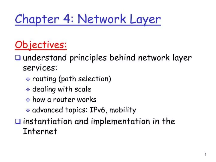
Chapter 4: Network Layer. Objectives: understand principles behind network layer services: routing (path selection) dealing with scale how a router works advanced topics: IPv6, mobility instantiation and implementation in the Internet. Introduction Virtual circuit and datagram networks

E N D
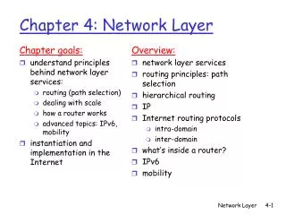
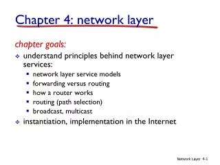
Chapter 4: Network Layer Objectives: • understand principles behind network layer services: • routing (path selection) • dealing with scale • how a router works • advanced topics: IPv6, mobility • instantiation and implementation in the Internet
Introduction Virtual circuit and datagram networks What’s inside a router IP: Internet Protocol Datagram format IPv4 addressing ICMP IPv6 Routing algorithms Link state Distance Vector Hierarchical routing Routing in the Internet RIP OSPF BGP Broadcast and multicast routing Chapter 4: Network Layer
transport segment from sending to receiving host on sending side encapsulates segments into datagrams on rcving side, delivers segments to transport layer network layer protocols in every host, router Router examines header fields in all IP datagrams passing through it network data link physical network data link physical network data link physical network data link physical network data link physical network data link physical network data link physical network data link physical application transport network data link physical application transport network data link physical Network layer
Key Network-Layer Functions analogy: • routing: process of planning trip from source to dest • forwarding: process of getting through single interchange • forwarding: move packets from router’s input to appropriate router output • routing: determine route taken by packets from source to dest. • Routing algorithms
routing algorithm local forwarding table header value output link 0100 0101 0111 1001 3 2 2 1 value in arriving packet’s header 1 0111 2 3 Interplay between routing and forwarding
Yet Another Network-Layer Function: Connection setup • 3rd important function in some network architectures: • ATM, frame relay, X.25 • Before datagrams flow, two hosts and intervening routers establish virtual connection • Routers get involved • Network and transport layer services: • Network: between two hosts • Transport: between two processes
Example services for individual datagrams: guaranteed delivery Guaranteed delivery with less than 40 msec delay Example services for a flow of datagrams: In-order datagram delivery Guaranteed minimum bandwidth to flow Restrictions on changes in inter-packet spacing Network service model Q: What service model for “channel” transporting datagrams from sender to rcvr?
Network layer service models: Guarantees ? Network Architecture Internet ATM ATM ATM ATM Service Model best effort CBR VBR ABR UBR Congestion feedback no (inferred via loss) no congestion no congestion yes no Bandwidth none constant rate guaranteed rate guaranteed minimum none Loss no yes yes no no Order no yes yes yes yes Timing no yes yes no no
Introduction Virtual circuit and datagram networks What’s inside a router IP: Internet Protocol Datagram format IPv4 addressing ICMP IPv6 Routing algorithms Link state Distance Vector Hierarchical routing Routing in the Internet RIP OSPF BGP Broadcast and multicast routing Chapter 4: Network Layer
Network layer connection and connection-less service • Datagram network provides network-layer connectionless service • Virtual circuit (VC) network provides network-layer connection service • Analogous to the transport-layer services, but: • Service: host-to-host • No choice: network provides one or the other • Implementation: in the core as well as the end-systems
call setup, teardown for each call before data can flow each packet carries VC identifier (not destination host address) every router on source-dest path maintains “state” for each passing connection link, router resources (bandwidth, buffers) may be allocated to VC “source-to-dest path behaves much like telephone circuit” performance-wise network actions along source-to-dest path Virtual circuits
VC implementation A VC consists of: • Path from source to destination • VC numbers, one number for each link along path • Entries in forwarding tables in routers along path • Packet belonging to VC carries a VC number. • VC number must be changed on each link. • New VC number comes from forwarding table
VC number 22 32 12 3 1 2 interface number Incoming interface Incoming VC # Outgoing interface Outgoing VC # 1 12 3 22 2 63 1 18 3 7 2 17 1 97 2 87 … … … … Forwarding table Forwarding table in northwest router: Routers maintain connection state information!
used to setup, maintain teardown VC used in ATM, frame-relay, X.25 not used in today’s Internet application transport network data link physical application transport network data link physical Virtual circuits: signaling protocols 6. Receive data 5. Data flow begins 4. Call connected 3. Accept call 1. Initiate call 2. incoming call
no call setup at network layer routers: no state about end-to-end connections no network-level concept of “connection” packets forwarded using destination host address packets between same source-dest pair may take different paths application transport network data link physical application transport network data link physical Datagram networks 1. Send data 2. Receive data
Forwarding table 4 billion possible entries Destination Address RangeLink Interface 11001000 00010111 00010000 00000000 through 0 11001000 00010111 00010111 11111111 11001000 00010111 00011000 00000000 through 1 11001000 00010111 00011000 11111111 11001000 00010111 00011001 00000000 through 2 11001000 00010111 00011111 11111111 otherwise 3
Longest prefix matching Prefix MatchLink Interface 11001000 00010111 00010 0 11001000 00010111 00011000 1 11001000 00010111 00011 2 otherwise 3 Examples Which interface? DA: 11001000 00010111 00010110 10100001 Which interface? DA: 11001000 00010111 00011000 10101010
Internet data exchange among computers “elastic” service, no strict timing req. “smart” end systems (computers) can adapt, perform control, error recovery simple inside network, complexity at “edge” many link types different characteristics uniform service difficult ATM evolved from telephony human conversation: strict timing, reliability requirements need for guaranteed service “dumb” end systems telephones complexity inside network Datagram or VC network: why?
Introduction Virtual circuit and datagram networks What’s inside a router IP: Internet Protocol Datagram format IPv4 addressing ICMP IPv6 Routing algorithms Link state Distance Vector Hierarchical routing Routing in the Internet RIP OSPF BGP Broadcast and multicast routing Chapter 4: Network Layer
Router Architecture Overview Two key router functions: • run routing algorithms/protocol (RIP, OSPF, BGP) • forwarding datagrams from incoming to outgoing link
Input Port Functions Decentralized switching: • given datagram dest., lookup output port using forwarding table in input port memory • goal: complete input port processing at ‘line speed’ • queuing: if datagrams arrive faster than forwarding rate into switch fabric Physical layer: bit-level reception Data link layer: e.g., Ethernet see chapter 5
Output Ports • Buffering required when datagrams arrive from fabric faster than the transmission rate • Scheduling discipline chooses among queued datagrams for transmission
Output port queueing • buffering when arrival rate via switch exceeds output line speed • queueing (delay) and loss due to output port buffer overflow!
Input Port Queuing • Fabric slower than input ports combined -> queueing may occur at input queues • Head-of-the-Line (HOL) blocking: queued datagram at front of queue prevents others in queue from moving forward • queueing delay and loss due to input buffer overflow!
Introduction Virtual circuit and datagram networks What’s inside a router IP: Internet Protocol Datagram format IPv4 addressing ICMP IPv6 Routing algorithms Link state Distance Vector Hierarchical routing Routing in the Internet RIP OSPF BGP Broadcast and multicast routing Chapter 4: Network Layer
Host, router network layer functions: • ICMP protocol • error reporting • router “signaling” • IP protocol • addressing conventions • datagram format • packet handling conventions • Routing protocols • path selection • RIP, OSPF, BGP forwarding table The Internet Network layer Transport layer: TCP, UDP Network layer Link layer physical layer
Introduction Virtual circuit and datagram networks What’s inside a router IP: Internet Protocol Datagram format IPv4 addressing ICMP IPv6 Routing algorithms Link state Distance Vector Hierarchical routing Routing in the Internet RIP OSPF BGP Broadcast and multicast routing Chapter 4: Network Layer
IP protocol version number 32 bits total datagram length (bytes) header length (bytes) type of service head. len ver length for fragmentation/ reassembly fragment offset “type” of data flgs 16-bit identifier max number remaining hops (decremented at each router) upper layer time to live Internet checksum 32 bit source IP address 32 bit destination IP address upper layer protocol to deliver payload to E.g. timestamp, record route taken, specify list of routers to visit. Options (if any) data (variable length, typically a TCP or UDP segment) IP datagram format how much overhead with TCP? • 20 bytes of TCP • 20 bytes of IP • = 40 bytes + app layer overhead
network links have MTU (max.transfer size) - largest possible link-level frame. different link types, different MTUs large IP datagram divided (“fragmented”) within net one datagram becomes several datagrams “reassembled” only at final destination IP header bits used to identify, order related fragments IP Fragmentation & Reassembly fragmentation: in: one large datagram out: 3 smaller datagrams reassembly
length =1500 length =1500 length =4000 length =1040 ID =x ID =x ID =x ID =x fragflag =0 fragflag =1 fragflag =1 fragflag =0 offset =0 offset =0 offset =370 offset =185 One large datagram becomes several smaller datagrams IP Fragmentation and Reassembly Example • 4000 byte datagram • MTU = 1500 bytes 1480 bytes in data field offset = 1480/8
Introduction Virtual circuit and datagram networks What’s inside a router IP: Internet Protocol Datagram format IPv4 addressing ICMP IPv6 Routing algorithms Link state Distance Vector Hierarchical routing Routing in the Internet RIP OSPF BGP Broadcast and multicast routing Chapter 4: Network Layer
IP address: 32-bit identifier for host, router interface interface: connection between host/router and physical link router’s typically have multiple interfaces host may have multiple interfaces IP addresses associated with each interface 223.1.1.2 223.1.2.1 223.1.3.27 223.1.3.1 223.1.3.2 223.1.2.2 IP Addressing: introduction 223.1.1.1 223.1.2.9 223.1.1.4 223.1.1.3 223.1.1.1 = 11011111 00000001 00000001 00000001 223 1 1 1
IP address classes • Class of an address is identified by first four bits
Example of Dotted Decimal Notation • Four decimal values per 32-bit address • Each decimal number • Represents eight bits • Is between 0 and 255
Division of the address space • Classing scheme does not yield equal number of networks in each class • For example, Class A: • First bit must be 0 • 7 remaining bits identify Class A net • 27 (= 128) possible class A nets
Classless Addressing • Subnet and Classless Addressing • Allow the division between prefix and suffix to occur on an arbitrary boundary • Address masks / subnet mask • 32-bit value, specifies the boundary
IP address: subnet part (high order bits) host part (low order bits) What’s a subnet ? device interfaces with same subnet part of IP address can physically reach each other without intervening router Subnets 223.1.1.1 223.1.2.1 223.1.1.2 223.1.2.9 223.1.1.4 223.1.2.2 223.1.1.3 223.1.3.27 LAN 223.1.3.2 223.1.3.1 network consisting of 3 subnets
Recipe To determine the subnets, detach each interface from its host or router, creating islands of isolated networks. Each isolated network is called a subnet. 223.1.1.0/24 223.1.2.0/24 223.1.3.0/24 Subnets Subnet mask: /24
How many? Subnets 223.1.1.2 223.1.1.1 223.1.1.4 223.1.1.3 223.1.7.0 223.1.9.2 223.1.9.1 223.1.7.1 223.1.8.1 223.1.8.0 223.1.2.6 223.1.3.27 223.1.2.1 223.1.2.2 223.1.3.1 223.1.3.2
host part subnet part 11001000 0001011100010000 00000000 200.23.16.0/23 IP addressing: CIDR CIDR:Classless InterDomain Routing • subnet portion of address of arbitrary length • address format: a.b.c.d/x, where x is # bits in subnet portion of address
IP addresses: how to get one? Q: How does network get subnet part of IP addr? A: gets allocated portion of its provider ISP’s address space ISP's block 11001000 00010111 00010000 00000000 200.23.16.0/20 Organization 0 11001000 00010111 00010000 00000000 200.23.16.0/23 Organization 1 11001000 00010111 00010010 00000000 200.23.18.0/23 Organization 2 11001000 00010111 00010100 00000000 200.23.20.0/23 ... ….. …. …. Organization 7 11001000 00010111 00011110 00000000 200.23.30.0/23
200.23.16.0/23 200.23.18.0/23 200.23.30.0/23 200.23.20.0/23 . . . . . . Hierarchical addressing: route aggregation Hierarchical addressing allows efficient advertisement of routing information: Organization 0 Organization 1 “Send me anything with addresses beginning 200.23.16.0/20” Organization 2 Fly-By-Night-ISP Internet Organization 7 “Send me anything with addresses beginning 199.31.0.0/16” ISPs-R-Us
200.23.16.0/23 200.23.18.0/23 200.23.30.0/23 200.23.20.0/23 . . . . . . Hierarchical addressing: more specific routes ISPs-R-Us has a more specific route to Organization 1 Organization 0 “Send me anything with addresses beginning 200.23.16.0/20” Organization 2 Fly-By-Night-ISP Internet Organization 7 “Send me anything with addresses beginning 199.31.0.0/16 or 200.23.18.0/23” ISPs-R-Us Organization 1
IP addressing: the last word... Q: How does an ISP get block of addresses? A: ICANN: Internet Corporation for Assigned Names and Numbers • allocates addresses • manages DNS • assigns domain names, resolves disputes
NAT: Network Address Translation rest of Internet local network (e.g., home network) 10.0.0/24 10.0.0.1 10.0.0.4 10.0.0.2 138.76.29.7 10.0.0.3 Datagrams with source or destination in this network have 10.0.0/24 address for source, destination (as usual) All datagrams leaving local network have same single source NAT IP address: 138.76.29.7, different source port numbers
NAT: Network Address Translation • Motivation: local network uses just one IP address as far as outside world is concerned: • no need to be allocated range of addresses from ISP: - just one IP address is used for all devices • can change addresses of devices in local network without notifying outside world • can change ISP without changing addresses of devices in local network • devices inside local net not explicitly addressable, visible by outside world (a security plus).
NAT: Network Address Translation Implementation: NAT router must: • outgoing datagrams:replace (source IP address, port #) of every outgoing datagram to (NAT IP address, new port #) . . . remote clients/servers will respond using (NAT IP address, new port #) as destination addr. • remember (in NAT translation table) every (source IP address, port #) to (NAT IP address, new port #) translation pair • incoming datagrams:replace (NAT IP address, new port #) in dest fields of every incoming datagram with corresponding (source IP address, port #) stored in NAT table
3 1 2 4 S: 10.0.0.1, 3345 D: 128.119.40.186, 80 S: 138.76.29.7, 5001 D: 128.119.40.186, 80 1: host 10.0.0.1 sends datagram to 128.119.40, 80 2: NAT router changes datagram source addr from 10.0.0.1, 3345 to 138.76.29.7, 5001, updates table S: 128.119.40.186, 80 D: 10.0.0.1, 3345 S: 128.119.40.186, 80 D: 138.76.29.7, 5001 NAT: Network Address Translation NAT translation table WAN side addr LAN side addr 138.76.29.7, 5001 10.0.0.1, 3345 …… …… 10.0.0.1 10.0.0.4 10.0.0.2 138.76.29.7 10.0.0.3 4: NAT router changes datagram dest addr from 138.76.29.7, 5001 to 10.0.0.1, 3345 3: Reply arrives dest. address: 138.76.29.7, 5001
NAT: Network Address Translation • 16-bit port-number field: • 60,000 simultaneous connections with a single LAN-side address! • NAT is controversial: • routers should only process up to layer 3 • violates end-to-end argument • NAT possibility must be taken into account by app designers, eg, P2P applications • address shortage should instead be solved by IPv6