Download
1 / 24
240 likes | 534 Views
Chapter 5: Wave Optics How to explain the effects due to interference, diffraction, and polarization of light? How do lasers work? Wave Optics Effects due to interference, diffraction, and polarization can not be explained by geometric optics.

E N D
Chapter 5: Wave Optics How to explain the effects due to interference, diffraction, and polarization of light? How do lasers work?
Wave Optics • Effects due to interference, diffraction, and polarization can not be explained by geometric optics. • Wave nature of light was demonstrated by Young’s double slit experiment (1820). In phase waves lead to constructive interference Out of phase waves lead to destructive interference
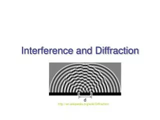
Two Wave Interference • What causes two identical waves to become “in-phase” or “out-of-phase”? • Path difference between the two waves! • Waves are in-phase when • P = 0, , 2, 3, …, n • Waves are out-of-phase when • P = /2, 3/2, 5/2, …, (n+1/2) Path difference P = (r2 – r1) http://www.physics.northwestern.edu/ugrad/vpl/waves/superposition2.html
Example: Two Wave Interference Path difference = 1 wavelength Path difference = 1/2 wavelength
Two Wave Interference (Contd.) Condition for constructive interference: n = 0, 1, 2, …
Two Wave Interference Pattern Intensity y n=0 n=1 n=2 www.Colorado.EDU/physics/2000/schroedinger/two-slit2.html
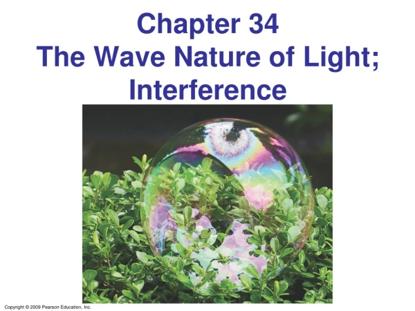
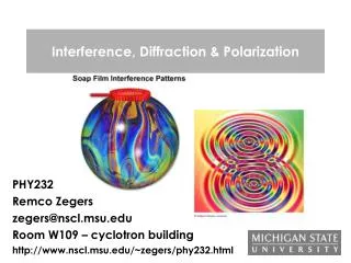
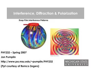
Thin Film Interference (Soap Bubbles) The phase difference of rays reflected from the top and bottom surfaces depends on the thickness and refractive index of the film, the angle at which the light strikes the film surface and the wavelength of the light.
Thin Film Interference (Antireflection coating) The substrate (glass, quartz, etc.) is coated with a thin layer of material so that reflections from the outer surface of the film and the outer surface of the substrate cancel each other by destructive interference.
Multiple Wave Interference – Diffraction Grating • Constructive interference occurs only when all waves are in-phase. • Path difference between any two successive waves must be nl. • Condition for interference maxima is, • Interference pattern has • sharp peaks. http://www.microscopy.fsu.edu/ primer/java/imageformation/ gratingdiffraction/index.html 2 slits 8 slits 16 slits
Diffraction Grating (Contd.) • Gratings have hundreds of slits per cm. • Applications in spectroscopy, crystallography etc. Diffraction pattern from a crystalline solid Diffraction of light from a CD Iridescence: A diffraction phenomenon
Review Problem A grating has 5000 lines/cm. A second order maximum is observed at 300. What is the wavelength of light? 500 nm
LASER: Light Amplification by Stimulated Emission of Light • Stimulated emission process was predicted by Einstein in 1916. First laser developed in 1959. • “Photons” and atoms can interact via the following processes. Absorption: Atom can absorb a photon and become excited. Spontaneous emission: Atom in excited state will spontaneously emit a photon and occupy a lower energy state. Stimulated emission: Atom in excited state is stimulated by a photon to emit another photon and occupy a lower energy state. Emitted photon has the same wavelength, phase, and direction as the stimulating photon. http://www.colorado.edu/physics/2000/lasers/lasers2.html
Stimulated Emission • Stimulated emission is more likely under “population inversion”. • Pumping: Process by which energy is supplied to excite more atoms to achieve population inversion. Atoms can be pumped by photon absorption, collisions, electric current…etc. PUMP Normal condition: Thermal equilibrium Population inversion achieved by “pumping” http://www.colorado.edu/physics/2000/lasers/lasers3.html
Laser Operation in a 3 Level System Excited Reservoir 1. Pumping: Excites atoms to highest level. Ground Excited 2. Fast radiative decay to reservoir creates population inversion between reservoir and ground states. Reservoir Ground Excited 3. Seed photon stimulates emission and light is amplified! Reservoir Laser light Ground http://www.phys.hawaii.edu/%7Eteb/optics/java/laser/index.html
Light Amplification • Light is amplified in a “resonant cavity” between two mirrors. • Photons from stimulated emission bounce between mirrors knocking out more photons. Light is “amplified”! Active Medium Laser Light 90% Reflecting Mirror 100% Reflecting Mirror http://www.colorado.edu/physics/2000/lasers/lasers4.html
Properties of Laser Light • High Power Density: At the focus, lasers can be thousands of times more intense than the sun! • Sunlight ~ 1300 W/m2 • Laser ~ 106 W/m2 • High Spectral purity: Light is emitted in a narrow band of wavelengths. This is due to the atomic processes in the “active medium”. • Small beam divergence: All photons travel in the same direction. Typical beam divergence ~ 2 x 10⁻⁵ degrees/m. • Coherence: All the emitted photons • bear a constant phase relationship • with each other in both time and space.
Types of Lasers • Solid state lasers, gas lasers, dye Lasers, semiconductor (diode) lasers. http://www.microscopy.fsu.edu/primer/lightandcolor/java.html
Holography (3D Imaging) 3D Object Film
Holography (2 Step Process) Reconstruction Recording Interference pattern is recorded on film. Need high resolution (slow) film, long exposure and vibration free set up. Interference pattern acts as a diffraction grating so different orders of maxima and minima reconstruct the image.
Polarization • Light is a “transverse” electromagnetic wave. • Polarization is the orientation of the electric field. • Note: • Natural light is “randomly” polarized. • Eye cannot distinguish different • polarizations.
Production of Polarized Light • Selective Absorption: • Note: Optically “active” materials can change the polarization direction. Example: Sugar solution, DNA, liquid crystals…etc.
Production of Polarized Light (Contd.) • Reflection: http://www.colorado.edu/physics/2000/applets/polarized.html
Production of Polarized Light • Scattering: • Light scattered in a perpendicular direction • is partially polarized!
Polarized Light: Some Applications • Mineral characterization. • Stress / strain fields (visual inspection of windshields). • Polarization microscopy. • Sunglasses / camera filters. • LCD displays. • Polarized art? http://www.colorado.edu/physics/2000/index.pl http://micro.magnet.fsu.edu/primer/virtual/polarizing/index.html